Tea processing equipment based on big data control
A kind of processing equipment and big data technology, which is applied in the field of tea processing equipment based on big data control, can solve the problems of easy accumulation of tea leaves, inability to push tea leaves, low efficiency of tea rolling, etc., and achieve the effect of convenient compression
- Summary
- Abstract
- Description
- Claims
- Application Information
AI Technical Summary
Problems solved by technology
Method used
Image

Examples
Example Embodiment
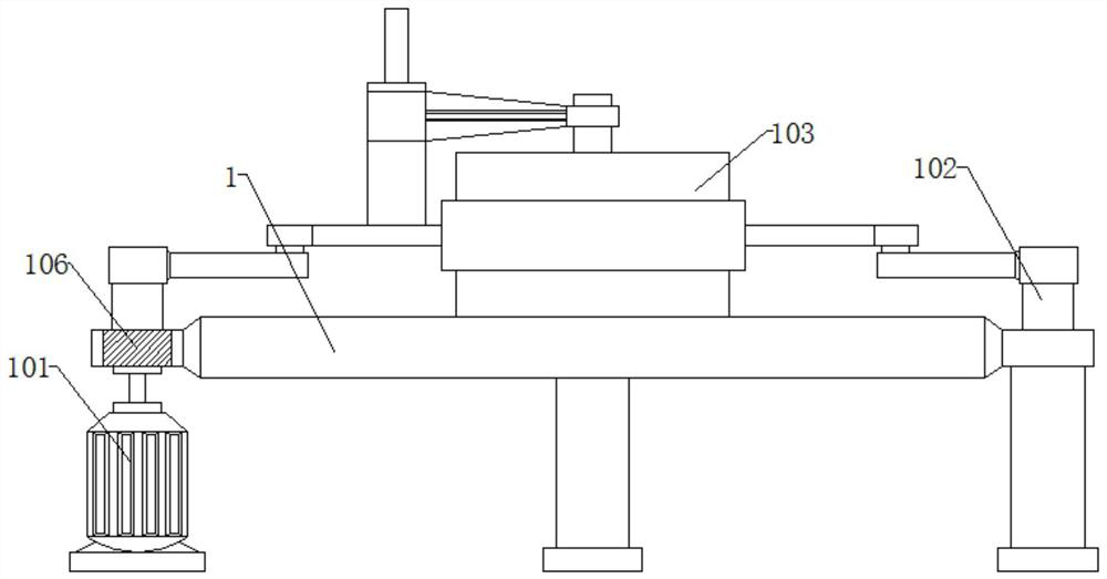
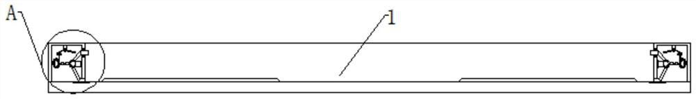
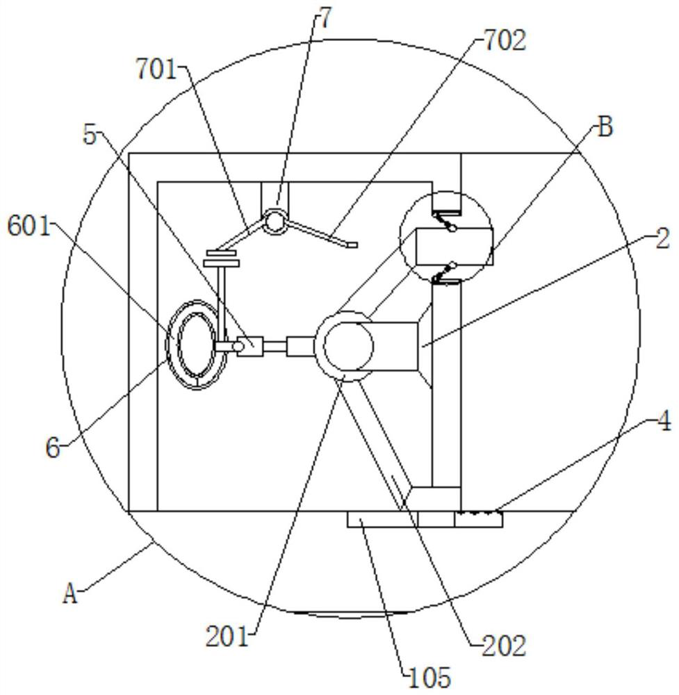
[0030]Example 1: The motor 101 is mounted on one side of the pulp 1, and the upper end of the motor 101 is rotated to be connected to the crank 102, and the inner swing of the crank 102 has a compression tea tube 103, and the outer side of the pulp 1 is embedded in the inner slide groove 105, and the disk The inside of the two sides is embedded in the outer slide 104, and the control module 106 is mounted on one side of the pulp 1, and the inner portion of the bracket 2 is mounted on the inside of the bracket 2, the inner swing of the bracket 2 has a first bearing 201, the first bearing The lower end of 201 has a scraper frame 202, and the upper end of the first bearing 201 is swinging having a swing rack 203, the control module 106 mounts the controller and processor, and the processor is connected to the external control terminal wireless signal connection, the control module 106 and The motor 101 is electrically connected, and the printer is formed in a concave configuration, and th
Example Embodiment
[0032]Example 2: The motor 101 is mounted on one side of the pulp 1, and the upper end of the motor 101 is rotated to be connected to the crank 102, and the inner side swing of the crank 102 has a compression tea tube 103, and the inner slide groove 105 is embedded on both sides of the pulp 1. The inside of the two sides is embedded in the outer slide 104, and the control module 106 is mounted on one side of the pulp 1, and the inner portion of the bracket 2 is mounted on the inside of the bracket 2, the inner swing of the bracket 2 has a first bearing 201, the first bearing The lower end of 201 is swinging a scraper frame 202, and the upper end of the first bearing 201 is swinging having a swing rack 203, and the upper and lower ends of the swing frame 203 are rotated to be connected to the second bearing 3, the inner swing of the second bearing 3 has sleeve 301, set The inner resilient connection of the cartridge 301 is formed with a spring 302, and the inner elastic connection of th
Example Embodiment
[0034]Example 3: The upper and lower ends of the oscillating frame 203 are rotated to be connected to the second bearing 3, and the inner swing of the second bearing 3 has the sleeve 301, the inner resilient connection of the sleeve 301, and the inner elastic connection of the spring 302 is slippery. The rod 303, the second bearing 3 is attached to one end of the outer slide 104, and the lower end of the scratch frame 202 is folded close to the side of the inner slide groove 105 folded with a folding plate 4, and the upper ends of the upper end of the folding plate are swinging a connecting frame. 401. The inner side of the connecting frame 401 is hingedly adjusted with a rotating bearing 402, and the inner portion of the pulp 1 is mounted, and the inner side of the circular ring 6 is embedded, and the first bearing 201 away from the side of the bracket 2 is swinged with telescopic rod 5. On one side of the telescoping rod 5, the rotary spherical 501 is hinged, and the rotary spherical
PUM
 Abstract
Description
Claims
Application Information
 - R&D Engineer
- R&D Manager
- IP Professional
- Industry Leading Data Capabilities
- Powerful AI technology
- Patent DNA Extraction
Browse by: Latest US Patents, China's latest patents, Technical Efficacy Thesaurus, Application Domain, Technology Topic.
© 2024 PatSnap. All rights reserved.Legal|Privacy policy|Modern Slavery Act Transparency Statement|Sitemap