V-Bank Air Filtration System Such as for Animal Confinement

Active Publication Date: 2011-12-22
PARKER HANNIFIN CORP
View PDF2 Cites 66 Cited by
  • Summary
  • Abstract
  • Description
  • Claims
  • Application Information

AI Technical Summary

Benefits of technology

[0010]In yet another aspect, embodiments of the invention provide a replaceable V-bank filter for use with a housing having an inlet opening and an outlet opening, with the housing having an outer upstream rectangular sealing surface and upper and lower retainers defining channels therein. An embodiment of the replaceable V-bank filter includes a generally rectangular frame having a peripheral and generally rectangular flange surrounding an inlet, a generally rectangular seal means along a first side of the flange for sealing against the rectangular sealing surface of the housing, and a generally rectangular seat means along a second side of the flange for seating against the upper and lower retainer. In at least one embodiment, the generall

Problems solved by technology

One of the challenges for the swine production industry is how to best provide the needed high-efficiency air filtration in a

Method used


Image

  • V-Bank Air Filtration System Such as for Animal Confinement
  • V-Bank Air Filtration System Such as for Animal Confinement
  • V-Bank Air Filtration System Such as for Animal Confinement

Examples


Embodiment Construction

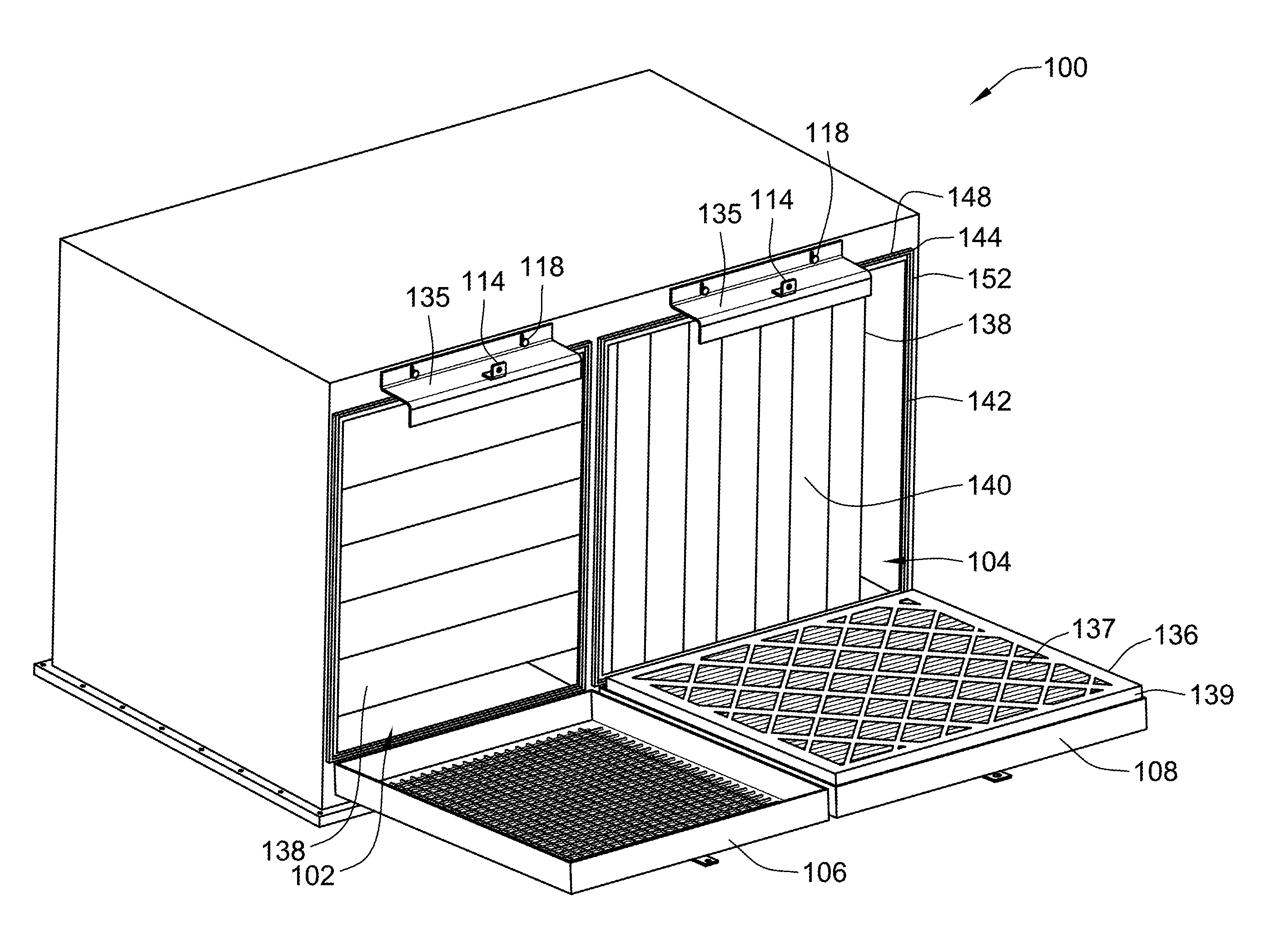
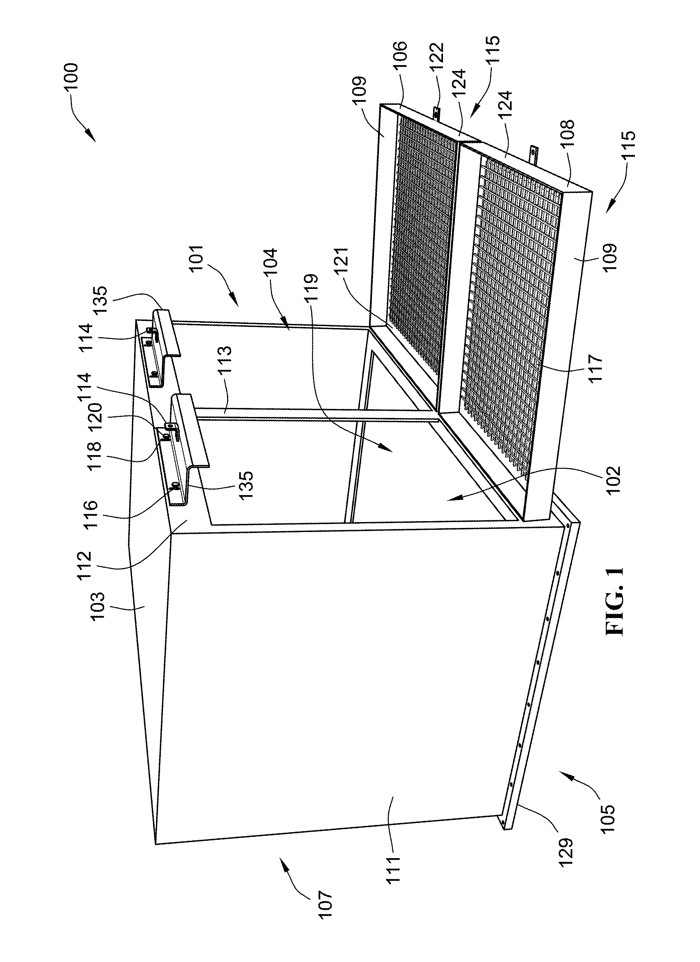
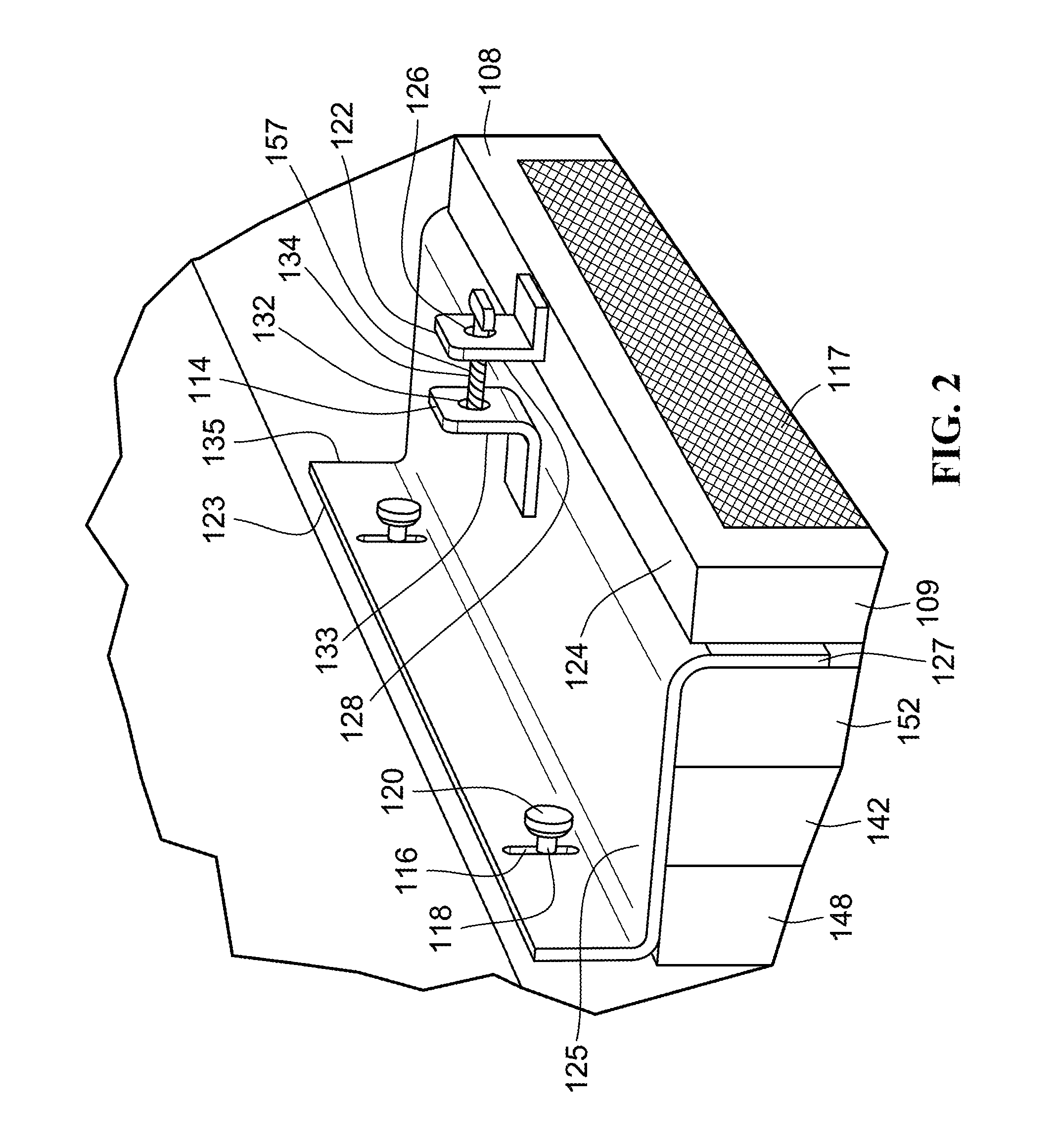
[0023]As shown in FIGS. 1-4 below, embodiments of the present invention include a filter housing with a pivoting door and a sliding latch that permit the quick removal and installation of V-bank filter elements, but also facilitate an airtight seal between the housing and filter element. The novel filter housing configuration described herein simplifies the maintenance, provides for a practical and reliable filter replacement process, and, thus, and may lower the costs associated with the operation of animal confinement facilities.

[0024]FIG. 1 illustrates a filter housing 100 for use in an animal confinement facility, constructed in accordance with an embodiment of the invention. In the embodiment shown, the filter housing 100 is substantially box-shaped, and may be formed from sheet metal or other suitable material. Filter housing 100 has a front side 101, a top side 103, a bottom side 105, a rear side 107, and two lateral sides 111. The front side 101 of the filter housing 100 has tw


PUM

PropertyMeasurementUnit
Fractionaaaaaaaaaa
Gravityaaaaaaaaaa
Perimeteraaaaaaaaaa

Abstract

A filter system includes a housing having an inlet opening surrounded by a sealing surface, an outlet opening, and a door having a seating surface surrounding a through-port opening. The door is movable between an open and closed position and a closed position. In an embodiment, a hinge connects the door to the housing, such that the door pivots between open and closed positions about the hinge. A panel pre-filter is seated along the seating surface of the door. A V-bank filter is positioned in the inlet opening, and has a flange in general alignment with the sealing surface, and has a plurality of filter media sections projecting away from the flange and into the housing interior. A latch is adapted to keep the panel pre-filter positioned inline and upstream of the V-bank filter. A seal is disposed between the flange of the V-bank filter and the sealing surface.

Description


Claims


Application Information

Patent Timeline
Owner PARKER HANNIFIN CORP
Why Eureka
Try Eureka