Labeling mechanism for reagent bottles

A reagent bottle and labeling technology, applied in the field of labeling equipment, can solve the problems of poor uniformity, unsightly products, no reagent bottle adjustment, etc., and achieve the effect of ensuring the uniformity

Inactive Publication Date: 2021-06-11
张寅豪
View PDF5 Cites 0 Cited by
  • Summary
  • Abstract
  • Description
  • Claims
  • Application Information

AI Technical Summary

Benefits of technology

This patented technology allows for efficient distribution of labels during production without interference or confusion caused by overlapping or misplaced products. It achieves these technical results by utilizing specialized containers called reactor drums (RH). These drums have different sizes and shapes depending upon their specific needs such as size, weight capacity, etc., allowing them to hold multiple smaller and lighter packages simultaneously. They allow for smooth transit of empty packets and improved efficiency in producing high volume items like liquid crystal displays. Additionally, they provide strict regulations regarding how many times certain types of chemical substance cartridges should go through before reaching the final destination where they will release gas onto glass substrates. Overall, this system improves productivity and quality control across various industries.

Problems solved by technology

Technological Problem: Current labeling methods involve vertical labelers with difficulty controlling the placement of reactants due to their tendency towards flowability during printing processes. These difficulties result in unevenness over time across different areas within the printed product's area.

Method used


Image

  • Labeling mechanism for reagent bottles
  • Labeling mechanism for reagent bottles
  • Labeling mechanism for reagent bottles

Examples


Embodiment Construction

[0037] Attached below Figure 1-8 The present invention is further described with embodiment:

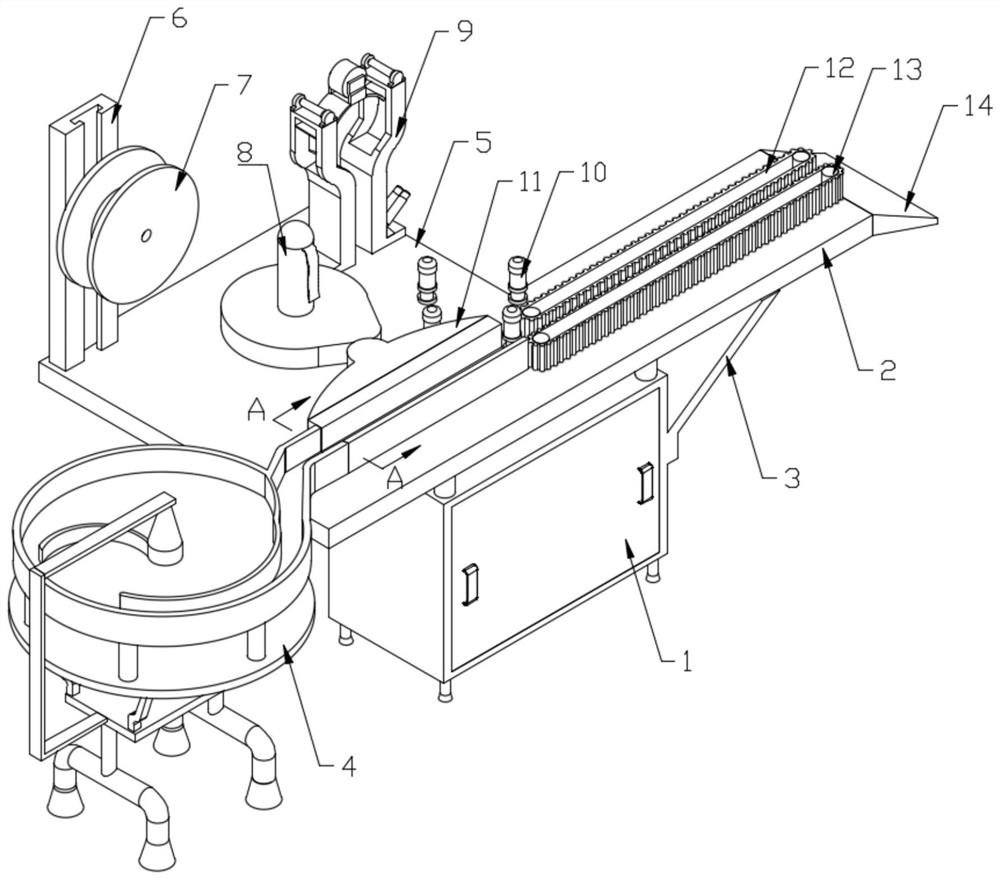
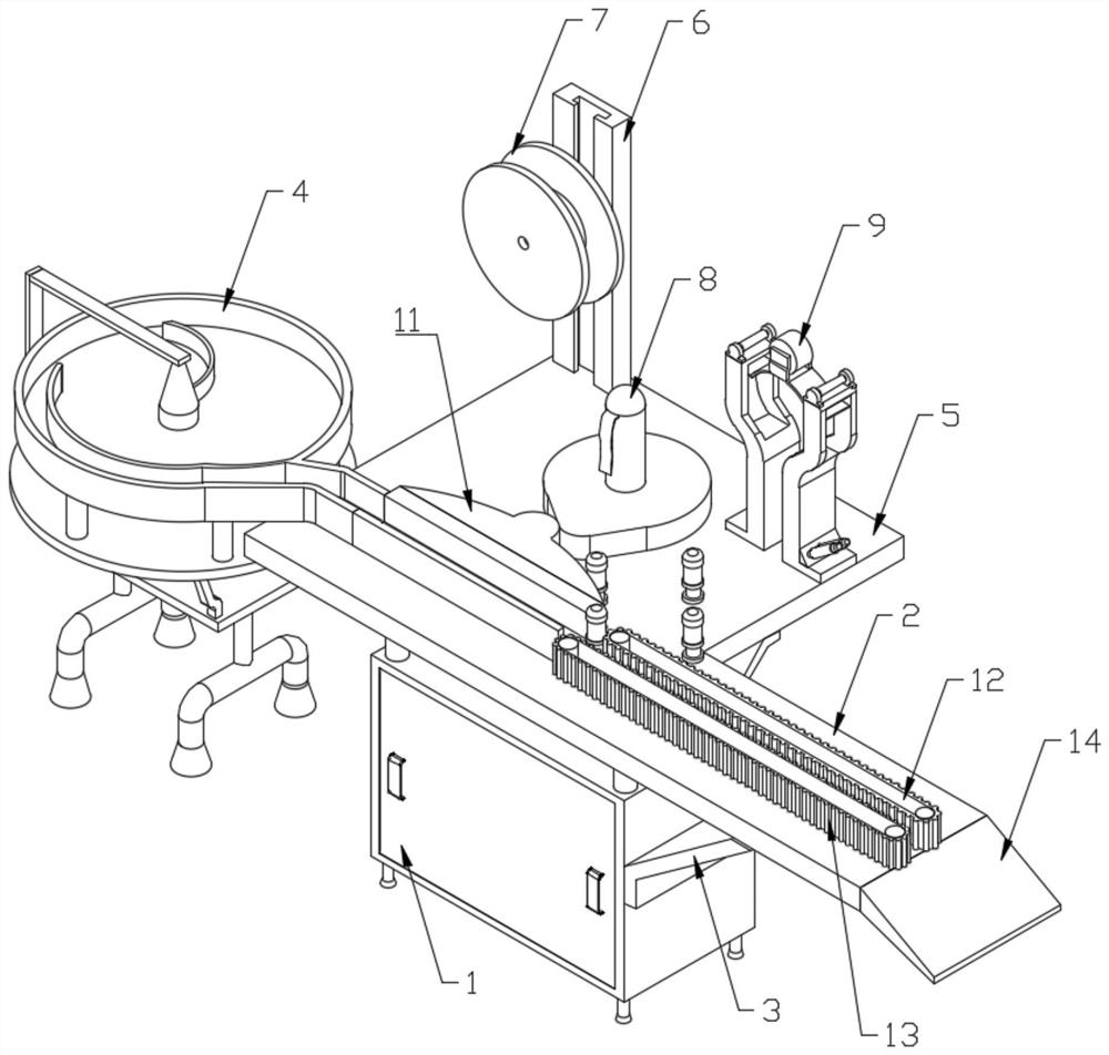
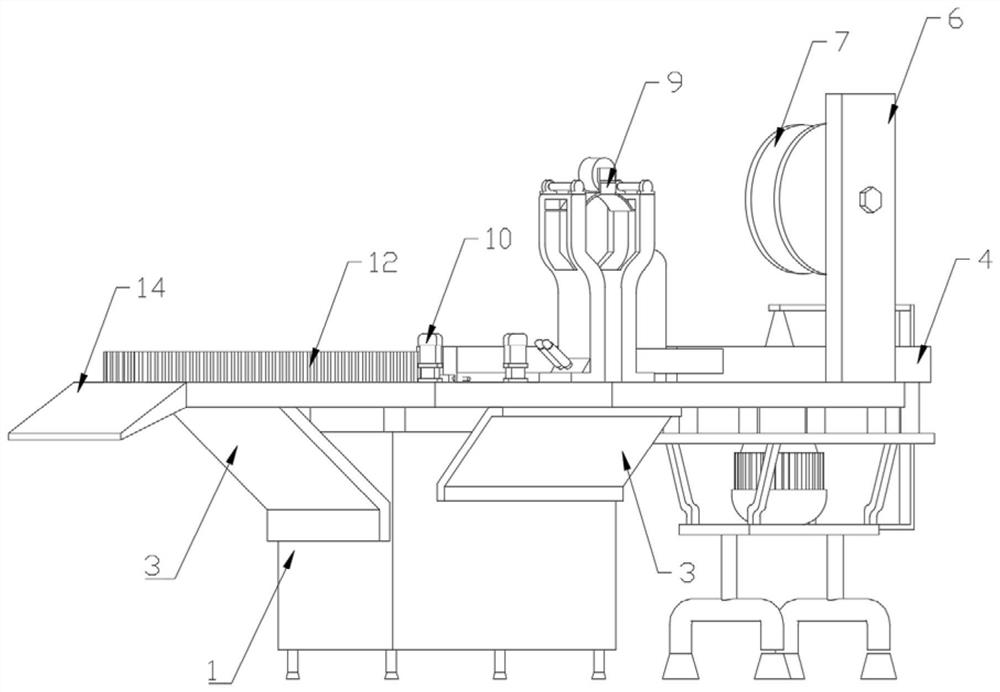
[0038]A labeling mechanism for reagent bottles, comprising a cabinet body 1, the bottom of the cabinet body 1 has four legs, and the top of the cabinet body 1 is horizontally fixed with a workbench 2; the bottom of the workbench 2 The support frame 3 is fixedly connected with the cabinet body 1; the rear side of the workbench 2 is also fixedly installed with a mounting table 5; the bottom of the mounting table 5 is fixedly connected with the cabinet body 1 through the support frame 3; the described One end of the workbench 2 is fixedly equipped with a reagent bottle lead-out plate 14, and the end of the workbench 2 far away from the reagent bottle lead-out plate 14 is provided with a reagent bottle arrangement transmission mechanism 4; the installation platform 5 is fixedly installed with a sliding mounting frame 6; The sliding mounting frame 6 is slidably connected with an unwinding


PUM


Abstract

The invention relates to a labeling mechanism for reagent bottles. The labelling mechanism comprises a machine box body, wherein a workbench is transversely and fixedly mounted at the top of the machine box body, and a reagent bottle arranging and conveying mechanism is arranged at the end, away from a reagent bottle guiding-out plate, of the workbench. Firstly, a large number of reagent bottles are placed in the reagent bottle arranging and conveying mechanism, a rotating motor drives the reagent bottles to start to rotate through a rotating disc, an arc-shaped elastic arc-shaped strip plays a role in blocking the reagent bottles during rotation; and under blocking of the arc-shaped elastic arc-shaped strip, the reagent bottles can only pass through a gap between the arc-shaped elastic arc-shaped strip and an outer shell; under the condition, more reagent bottles can be blocked, so that the condition that the reagent bottles topple over can be prevented, part of the reagent bottles can be ensured to be attached to the inner wall of the outer shell to be arranged in sequence, and the reagent bottles can be ensured to enter the reagent bottle guide-out channel in order.

Description


Claims


Application Information

Patent Timeline
Owner 张寅豪
Why Eureka
Try Eureka