Automatic equipment feeding intelligent control system
A technology of intelligent control system and automation equipment, used in portable lifting devices, load hanging components, hoisting devices, etc., can solve many problems such as time-fixed binding, etc., to improve service life, improve safety factor, and quickly fix Effect
- Summary
- Abstract
- Description
- Claims
- Application Information
AI Technical Summary
Benefits of technology
Problems solved by technology
Method used
Image

Examples
Embodiment 1
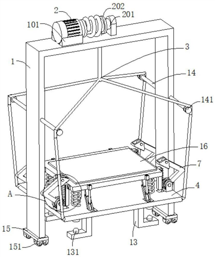
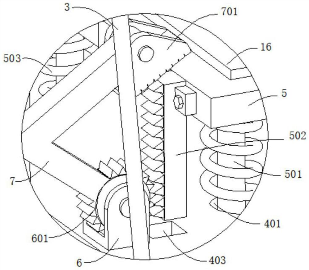
[0035] refer to figure 1 , figure 2 , image 3 and Figure 6 , an intelligent control system for feeding automation equipment, including a U-shaped frame 1, the top of the U-shaped frame 1 is connected with a motor base 101, the inner wall of the motor base 101 is connected with a drive motor 2, and the output end of the drive motor 2 is connected with a rotating shaft 201. The outer wall of the shaft 201 is sleeved with a take-up roller 202, the outer wall of the take-up roller 202 is connected with a rope 3, the end of the rope 3 far away from the take-up roller 202 is connected with a bottom plate 4, the outer wall of the bottom plate 4 is dug with a through hole 401, and the outer wall of the bottom plate 4 is connected with a sleeve The pipe 402 and the sleeve 402 are placed on the lower side of the through hole 401, the sleeve 402 is movably connected with a straight rod 501, the top of the straight rod 501 is connected with a support plate 5, and the outer wall of the s
Embodiment 2
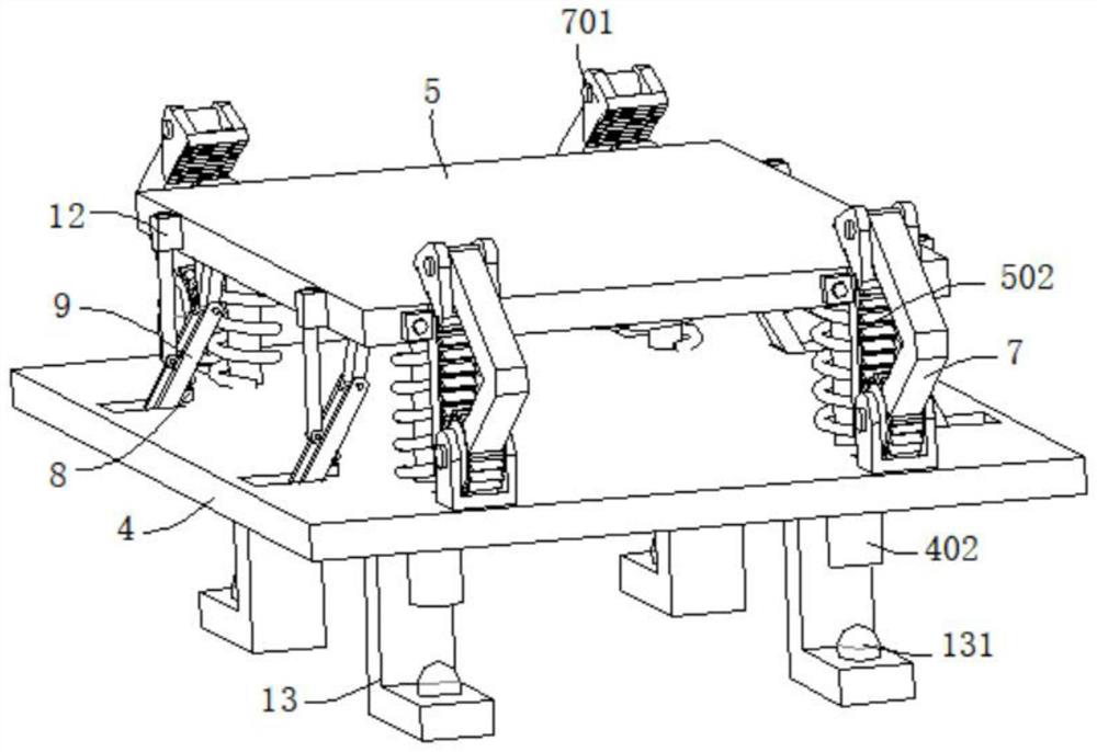
[0041] refer to Figure 1-5 , the automatic equipment feeding intelligent control system is basically the same as that of Embodiment 1, furthermore, the outer wall of the base plate 4 is connected with a support rod 8, and the end of the support rod 8 away from the base plate 4 is movably connected with a swing plate 9, and the outer wall of the swing plate 9 rotates Connected with a support plate 10, the end of the support plate 10 away from the swing plate 9 is fixedly connected to the bottom wall of the support plate 5, the outer wall of the swing plate 9 is movably connected with a stop rod 11, and the outer wall of the support plate 5 is connected with a limit block 12, a limit block 12 The outer wall is excavated with a concave hole matched with the blocking rod 11 .
[0042] The outer wall of the swing plate 9 is dug with a chute 901, the inner wall of the chute 901 is slidably connected with a slider 902, the outer wall of the slider 902 is excavated with a movable groove
Embodiment 3
[0046] refer to figure 1 and Figure 7 , an intelligent control system for automatic equipment feeding, which is basically the same as in Embodiment 1. Furthermore, the rope 3 includes a main rope 301 and four sub-ropes 302. The main rope 301 is wound and connected to the outer wall of the take-up roller 202. The main rope 301 One end away from the take-up roller 202 is connected to the four sub-ropes 302, and the end of the four sub-ropes 302 away from the main rope 301 is connected to the bottom plate 4; by connecting the four sub-ropes 302 to the four corners of the bottom plate 4, it is convenient to improve the loading of the board. When the stability, to avoid its shaking.
[0047] U-shaped frame 1 outer wall is connected with connecting rod 14, and connecting rod 14 outer wall is connected with fixed pulley 141, and sub-rope 302 is slidably connected on the outer wall of fixed pulley 141; The moving direction of sub-rope 302 is guided.
[0048] Both the support plate 5 a
PUM
 Abstract
Description
Claims
Application Information
 - R&D Engineer
- R&D Manager
- IP Professional
- Industry Leading Data Capabilities
- Powerful AI technology
- Patent DNA Extraction
Browse by: Latest US Patents, China's latest patents, Technical Efficacy Thesaurus, Application Domain, Technology Topic.
© 2024 PatSnap. All rights reserved.Legal|Privacy policy|Modern Slavery Act Transparency Statement|Sitemap