Chain transmission

A transmission, chain technology, applied in the direction of vehicle transmission, chain/belt drive, transportation and packaging, etc., can solve problems such as complex structure

Pending Publication Date: 2021-09-21
张卫
View PDF0 Cites 0 Cited by
  • Summary
  • Abstract
  • Description
  • Claims
  • Application Information

AI Technical Summary

Problems solved by technology

[0003] In order to overcome the disadvantages of the existing bicycle transmission with complex structure, the present invention provides a chain transmission, which can adjust th

Method used


Image

  • Chain transmission
  • Chain transmission
  • Chain transmission

Examples


Embodiment Construction

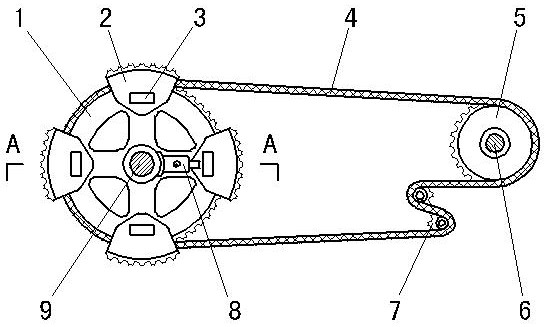
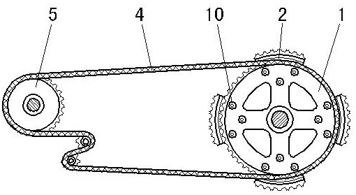
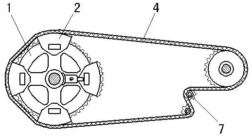
[0020] exist figure 1 , figure 2 , Figure 4 , Figure 7 , Figure 8 , Figure 9 Among them, the driving wheel 1 and the driven wheel 5 are respectively connected on the front axle 9 and the rear axle 6 which are arranged in parallel front and back, and the said driving wheel 1 and the driven wheel 5 are all sprocket structures. The chain 4 is connected on the driving wheel 1 and the driven wheel 5, and the tension wheel 7 is connected with the chain 4. The speed change plate 2 has a fan-shaped plate surface structure, and the arc-shaped edges of the speed change plate 2 and the fan-shaped plate surface form a left-upper-right-down stepped plate structure. The arc-shaped side of the transmission plate 2 is set as an arc-shaped sprocket rack structure, and the sprockets on the transmission plate 2 have the same structure as the sprockets on the driving wheel 1 and the driven wheel 5 . Several speed change plates 2 are arranged on the left side of driving wheel 1 and evenly


PUM


Abstract

The invention provides a chain transmission. A chain is connected to a driving wheel and a driven wheel, and a tensioning wheel is connected with the chain. And a plurality of fan-shaped speed change plates are uniformly arranged on the left side of the driving wheel gear ring and are connected with the driving wheel in a left-right inserting manner. Arc-shaped edges on the speed change plates are arranged to be of chain rack structures, and chain racks on all the speed change plates are located at the outer ends of the gear rings on the driving wheels. A transmission head is arranged on each speed change plate, and a left through groove, a working groove and a right through groove are formed in the bottom end face of each transmission head. The adjuster is connected to a shaft sleeve of the rotating shaft, and a piston rod in the adjuster corresponds to the bottom end face of each transmission head. When the driving wheel drives the speed change plate and the transmission head to rotate forwards or backwards around the rotating shaft, the piston rod on the adjuster can be matched with the working groove in the transmission head to push the speed change plate to be overlapped with or separated from the driving wheel. The speed change plate overlapped with the driving wheel can change the perimeter of the driving wheel in a chain rack adding mode, and therefore the chain transmission speed can be adjusted.

Description


Claims


Application Information

Patent Timeline
Owner 张卫
Why Eureka
Try Eureka