Multi-angle hole opening device for porous steel plate

A multi-angle, baffle technology, applied in the direction of positioning devices, feeding devices, automatic control devices, etc., can solve the problems of low processing accuracy, waste of labor, low work efficiency, etc., to reduce vibration and wear, and avoid the decline of drilling accuracy , reduce the effect of high temperature

Inactive Publication Date: 2021-11-02
ANHUI TECHN COLLEGE OF MECHANICAL & ELECTRICAL ENG
View PDF0 Cites 1 Cited by
  • Summary
  • Abstract
  • Description
  • Claims
  • Application Information

AI Technical Summary

Benefits of technology

This patented technology allows for precise control over how much pressure needs to be applied when cutting holes into materials such as metal or plastic material. It achieves this by controllably moving tools towards each other based upon their size and shape. Additionally, it uses various types of motors like electricity-power hybrid systems (EPS) to achieve these movements without causing excessive heat generation due to friction between components. Overall, this technology improves efficiency and accuracy in machining operations.

Problems solved by technology

The technical problem addressed by this patented technology relates to improving the precision and speed with traditional methods for drilling complex structures such as turbine blades or pipes that require multiple steps involving cutting tools along their entire length before being assembled into final products. This results in wasted effort and increased errors during assembly processes caused by manual adjustments made manually overtime.

Method used


Image

  • Multi-angle hole opening device for porous steel plate
  • Multi-angle hole opening device for porous steel plate
  • Multi-angle hole opening device for porous steel plate

Examples


Embodiment Construction

[0077] The following description is used to disclose the invention to enable those skilled in the art. Preferred embodiments in the following description are only example, and those skilled in the art can think of other obvious variations.

[0078] In order to solve how to drill three pairs of angles workpiece drilling technical problems, such as Figure 1 ~ 6 Shown provide the following technical solutions:

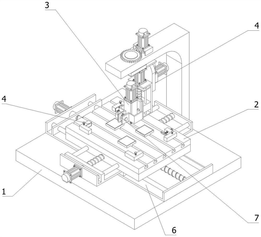
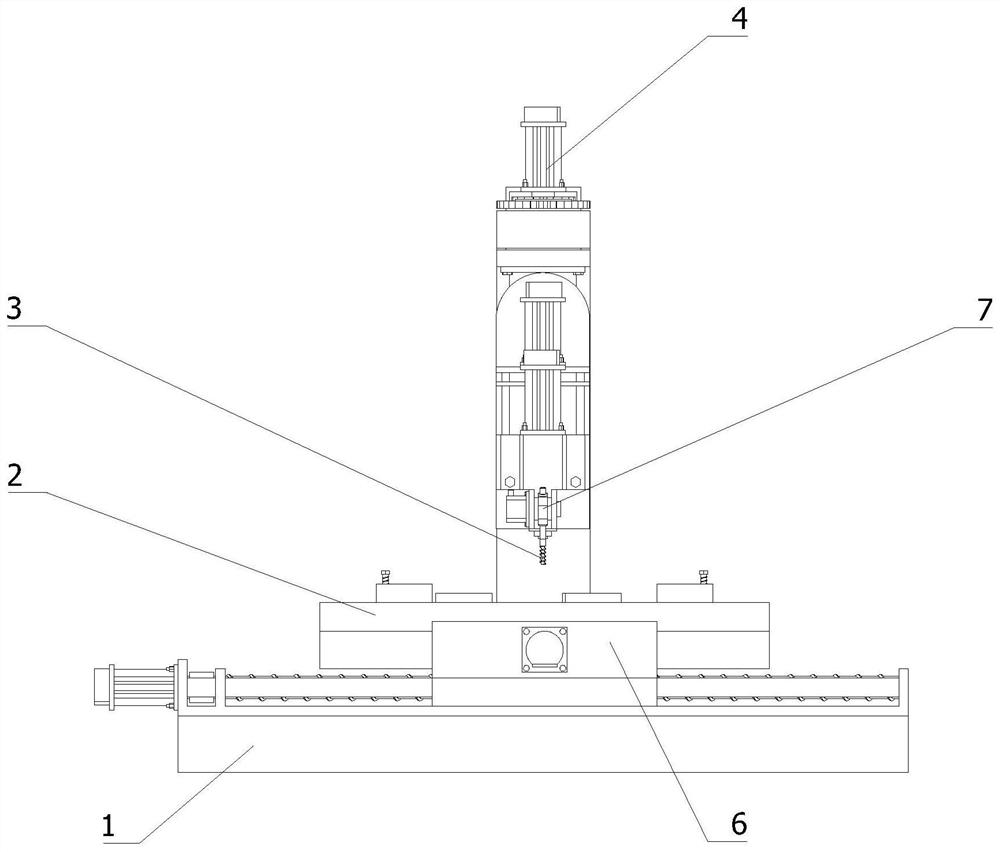
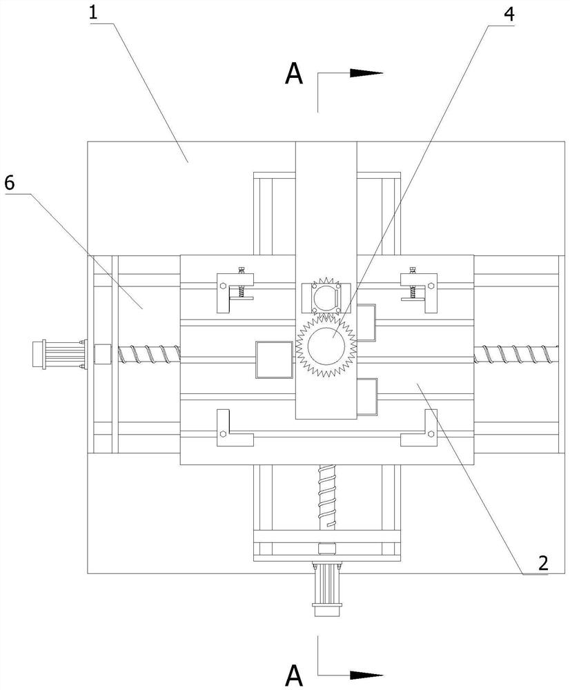
[0079] A multi-angle aperture means porous workpieces, comprising a table, fixture 2 and the drill 3, further comprising angle adjustment device 4, the angle adjustment device 4 comprises,

[0080] Mount 4a, 4a disposed on the mount table 1, and is located directly above the fixture 2;

[0081] On the mounting base 4a, 4b mount the first rotary table 4a rotatably connected to a first rotary disc 4b, 4b of the first rotary disc is provided with a vertical axis;

[0082] A first rotary drive 4c, 4c fixed to a first rotary drive provided on the mounting base 4a, 4b for rotating the


PUM


Abstract

The invention relates to the technical field of machining tools, in particular to a multi-angle hole opening device for a porous steel plate. The device comprises a workbench, a tool clamp and a drilling machine, and further comprises angle adjusting equipment which comprises a mounting base arranged on the workbench and located over the tool clamp, a first rotating disc, a first rotating driver, a second rotating disc, a second rotating driver, a first linear driver and a first sliding block. The axis of the first rotating disc is vertically arranged on the mounting base, and the first rotating disc is rotatably connected with the mounting base; the first rotating driver is fixedly arranged on the mounting base and is used for driving the first rotating disc to rotate along the axis of the first rotating disc; the axis of the second rotating disc is horizontally arranged on the first rotating disc; the second rotating driver is fixedly arranged on the first rotating disc and is used for driving the second rotating disc to rotate along the axis of the second rotating disc; the first linear driver is fixedly arranged on the second rotating disc; and the first sliding block is arranged at the output end of the first linear driver and fixedly connected with a drilling machine, and an output shaft of the drilling machine is coaxial with the first rotating disc. The multi-angle hole opening precision of the steel plate is improved.

Description


Claims


Application Information

Patent Timeline
Owner ANHUI TECHN COLLEGE OF MECHANICAL & ELECTRICAL ENG
Why Eureka
Try Eureka