Vacuum capacitor capable of changing capacitance

A vacuum capacitor and capacitor capacity technology, applied in the electronic field, can solve problems affecting the service life and use cost of vacuum capacitors, affecting the production efficiency of semiconductor chips, and inaccurate adjustment of capacitor value, so as to shorten the capacitor adjustment time and facilitate long-term stability The effect of fast use and adjustment speed

Pending Publication Date: 2021-12-07
上海华盈实科技有限公司
View PDF0 Cites 2 Cited by
  • Summary
  • Abstract
  • Description
  • Claims
  • Application Information

AI Technical Summary

Benefits of technology

This patented technology allows for precise control over how much electricity flows into or out from an inductively driven device (VCO) while creating a magnetically induced motion that changes its shape when subjected to varying levels of voltage applied across them. By setting certain values on these variables, this technology can be used with various types of devices like VCOs, amplifiers, filters, phase locked loops, etc., resulting in improved performance and reliability during operation. Additionally, there are improvements made to make the design smaller but still maintain good quality components within the overall product's space constraints. Overall, this new technology improves manufacturing efficacy and yields of semi conductors chips.

Problems solved by technology

This patented technical problem addressed in this patents relates to improving the accuracy and reliability of changing the capacity (the amount of space inside) within an electronic device called a vacuump capacitor without causing damage or decreased functionality caused by repeated operation over multiple cycles.

Method used


Image

  • Vacuum capacitor capable of changing capacitance
  • Vacuum capacitor capable of changing capacitance
  • Vacuum capacitor capable of changing capacitance

Examples


Embodiment 1

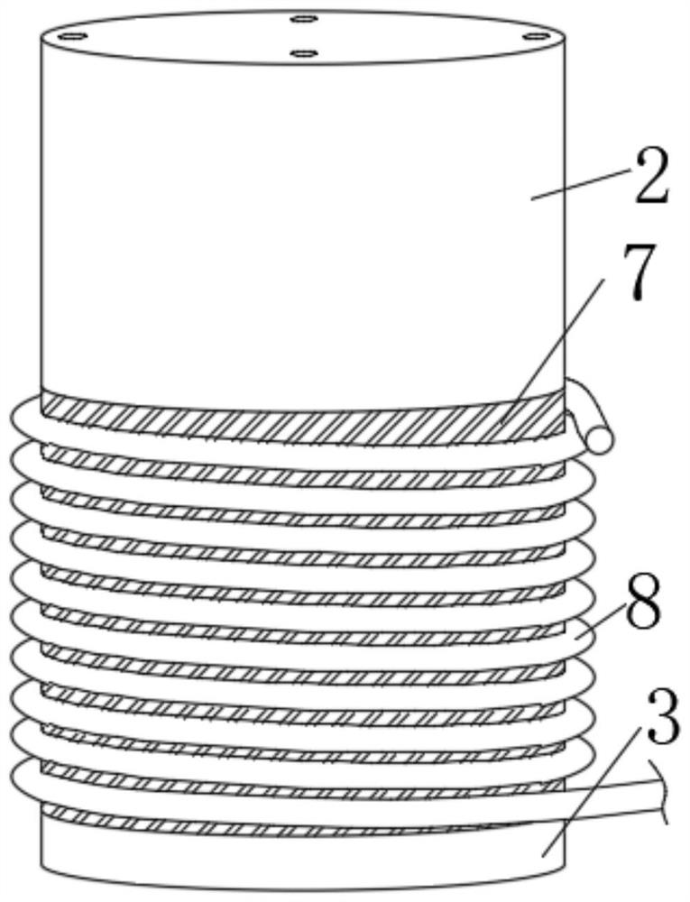
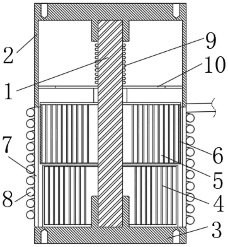
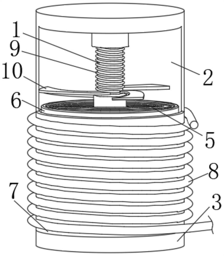
[0038] see Figure 1-Figure 5 , a vacuum capacitor that can change the capacitance, including an insulating rod 1, an upper case 2, a lower case 3, a fixed electrode 4, a movable electrode 5, a magnet 6, an insulating shell 7, a voice coil motor coil 8, a spring 9 and the moving electrode connection piece 10, the top of the insulating rod 1 is connected with the upper case 2, and the bottom of the insulating rod 1 is installed with the lower case 3, and the top of the lower case 3 is connected with the fixed electrode 4, the volume of the vacuum capacitor Smaller, and when adjusting the capacitor capacity, the adjustment speed is fast, the accuracy is high, and the external dimensions of the vacuum capacitor that can change the capacitor capacity are 130mm in length × 73mm in diameter, and the mass m = 1.2 kg;

[0039] The top of the fixed electrode 4 is provided with a movable electrode 5, and the outer wall of the movable electrode 5 is connected with a magnet 6. The direction

Embodiment 2

[0053] In order to compare the parameter difference between this embodiment and the existing vacuum capacitor whose capacitance can be changed, compare the existing capacitor model SCV-205G with the vacuum capacitor whose capacitance can be changed in this embodiment:

[0054] The external dimension of the vacuum capacitor whose capacitor model is SCV-205G is set to be 140 mm in length x 73 mm in diameter, and the weight is W=1.3 kg. The polar height h of the two capacitors is 0-35 mm. Rotate one circle, the moving electrode moves 2.9 mm, 35 mm-500 picofarads, that is, 1 mm-14.3 picofarads, 12 circles-500 picofarads, then 1 circle-41.7 picofarads, that is, rotate one circle, the moving electrode moves 2.9 mm, the capacitance capacity changes by 41.47 picofarads.

[0055] In this embodiment, the external dimensions of the variable vacuum capacitor are 130 mm long x 73 mm in diameter, and the mass m=1.2 kg. When the force generated by the coil 8 of the voice coil motor and the forc


PUM


Abstract

The invention relates to the technical field of electronics, and discloses a vacuum capacitor capable of changing capacitance, which comprises an insulating rod, an upper shell, a lower shell, a fixed electrode, a movable electrode, a magnet, an insulating shell, a voice coil motor coil, a spring and a movable electrode connecting piece. The top end of the insulating rod is connected with the upper shell, and the bottom end of the insulating rod is provided with the lower shell. According to the invention, the coil of the voice coil motor is electrified, so that the coil of the voice coil motor generates a driving force magnetic field under the action of current, the magnet generates an induced electromotive force, and under the action of the induced electromotive force, the movable electrode moves in the direction perpendicular to the current direction of the coil of the voice coil motor because the current of the coil of the voice coil motor is different; therefore, the relative area between the movable electrode and the fixed electrode is changed, the capacity of the capacitor can be rapidly changed, and compared with an existing variable vacuum capacitor, the variable vacuum capacitor has the advantages of being high in adjusting speed (50-500 ms) and high in position accuracy.

Description


Claims


Application Information

Patent Timeline
Owner 上海华盈实科技有限公司
Why Eureka
Try Eureka