Low-emission backflow combustion chamber adopting circumferential and tangential oil supply mode

A recirculation combustion chamber, low-emission technology, applied in the field of aero-engines, can solve the problems of low pressure loss, large nozzle spacing ratio, difficult low-polluting combustion solutions, etc., to ensure transition state characteristics, small radial size, and low pollution. Potential inhibiting effect

Active Publication Date: 2022-01-04
ZHEJIANG UNIV
View PDF7 Cites 0 Cited by
  • Summary
  • Abstract
  • Description
  • Claims
  • Application Information

AI Technical Summary

Problems solved by technology

For the return combustion chamber of small and medium-sized turboshaft/turboprop engines, it is difficult to directly implement the turbofan engine center due to the characteri

Method used


Image

  • Low-emission backflow combustion chamber adopting circumferential and tangential oil supply mode
  • Low-emission backflow combustion chamber adopting circumferential and tangential oil supply mode
  • Low-emission backflow combustion chamber adopting circumferential and tangential oil supply mode

Examples


Embodiment Construction

[0023] Below in conjunction with accompanying drawing and embodiment, technical scheme of the present invention is described further:

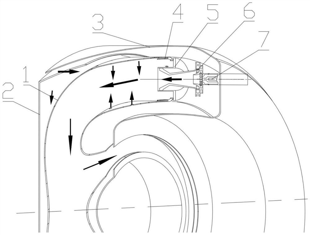
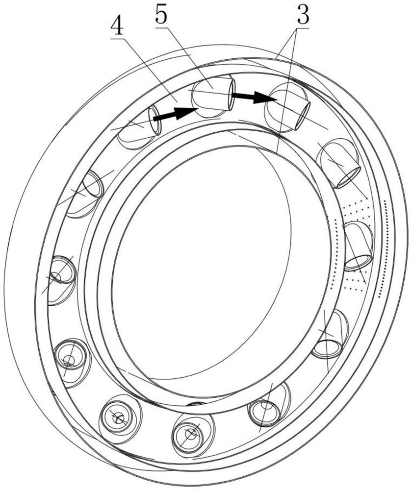
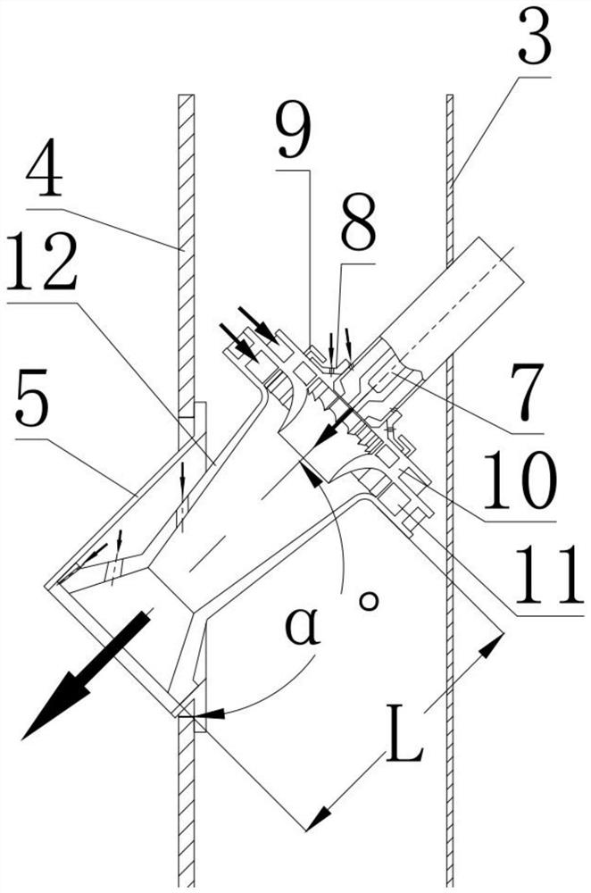
[0024] Such as Figure 1-2 Shown is a low-emission recirculation combustor with circumferential tangential oil supply, including: flame tube elbow 1, radial diffuser 2, combustion chamber casing 3, flame tube head 4, swirl installation Seat 5, oblique premixing vortex 6 and fuel nozzle 7, the radial diffuser 2 is installed inside the combustion chamber casing 3 from the tail end forward, and the flame tube elbow 1 is placed in the Inside the radial diffuser 2, the head end of the flame tube elbow 1 is provided with the flame tube head 4, the flame tube head 4 is provided with the vortexer mounting seat 5, and the chamfered pre-cut The vortex mixer 6 is installed in the vortex mixer mounting seat 5 , and the fuel nozzle 7 communicates with the flame cylinder elbow 1 through the obliquely cut premix vortex 6 .

[0025] Such as image 3 As shown,


PUM


Abstract

The invention discloses a low-emission backflow combustion chamber adopting a circumferential and tangential oil supply mode, and relates to the technical field of aero-engines. The low-emission backflow combustion chamber comprises a flame tube elbow, a radial diffuser, a combustion chamber casing, a flame tube head, a swirler mounting seat, a beveled premixing swirler and a fuel nozzle. The radial diffuser is mounted in the combustion chamber casing from the tail end to the front end, the flame tube elbow is arranged in the radial diffuser, the flame tube head is arranged at the head end of the flame tube elbow, the swirler mounting seat is arranged on the flame tube head, the beveled premixing swirler is mounted in the swirler mounting seat, and the fuel nozzle communicates with the flame tube elbow through the beveled premixing swirler. The characteristics that the axial length of the backflow combustion chamber is large and the cavity height of a flame tube is small are fully utilized for fuel oil grading, the ignition and flameout characteristics and the transition state characteristics are guaranteed in the limited backflow combustion chamber space, and low emission of pollutants is achieved.

Description


Claims


Application Information

Patent Timeline
Owner ZHEJIANG UNIV
Why Eureka
Try Eureka