Survey instrument for determining 3D coordinates, distance measurement method and computer program product

A technology of distance measurement and instrumentation, applied in geodesy, industrial metrology, and surveying instrumentation

Pending Publication Date: 2022-01-11
HEXAGON TECH CENT GMBH
View PDF4 Cites 0 Cited by
  • Summary
  • Abstract
  • Description
  • Claims
  • Application Information

AI Technical Summary

Problems solved by technology

According to the prior art, it is known, for example, that an asymmetrical emitter opening reduces said problem, since the emitted beam is a point-asymmetrical mirror image

Method used


Image

  • Survey instrument for determining 3D coordinates, distance measurement method and computer program product
  • Survey instrument for determining 3D coordinates, distance measurement method and computer program product
  • Survey instrument for determining 3D coordinates, distance measurement method and computer program product

Examples


Embodiment Construction

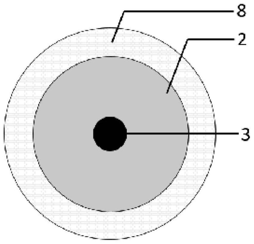
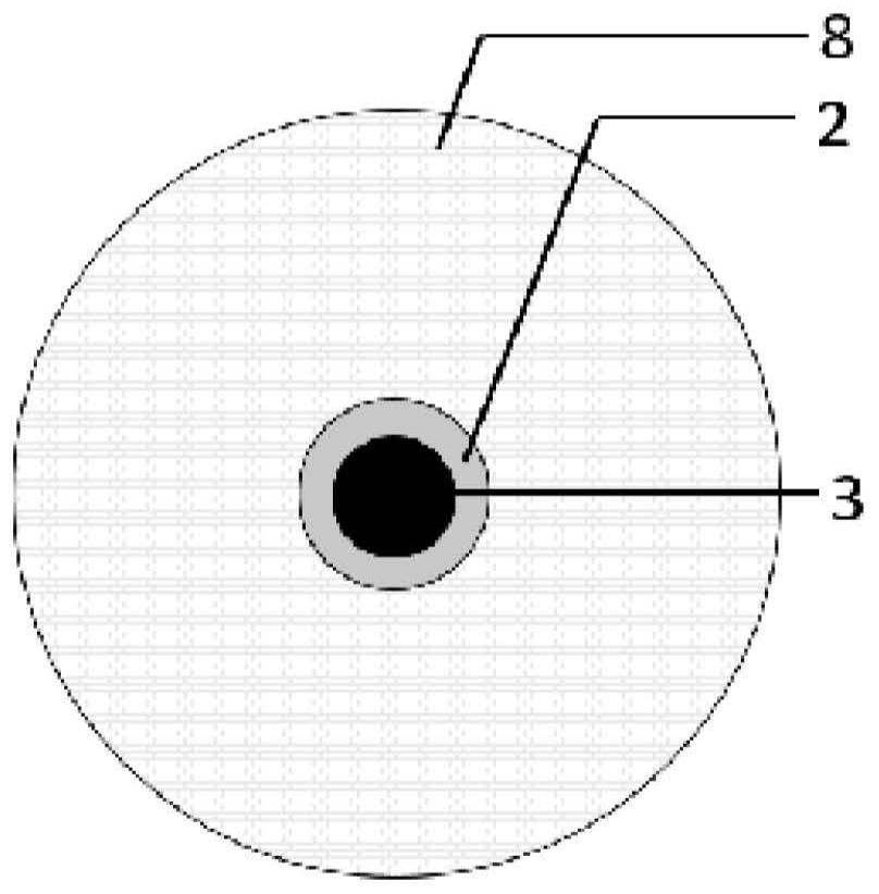
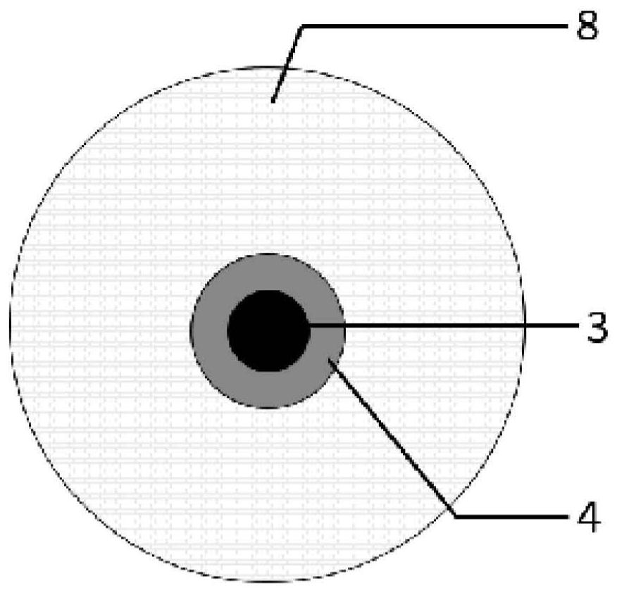
[0056] Figure 1a to Figure 1d shows the use of divergent measurement beams ( Figure 1a and Figure 1b ) and the collimated measurement beam ( Figure 1c and Figure 1d ) performed distance measurement, the distance to the target is 2m ( Figure 1b and Figure 1d ) and 18m ( Figure 1a and Figure 1c ) for an exemplary visualization of the occlusion 3 at the aperture of the telescope front lens 8, where the measurement is performed in the on-target state, so that the aiming axis of the telescope is aligned with the optical center of the retroreflector. Figure 1a The occlusion or occlusion 3 at the aperture of the telescope lens or lens group 8 of the diverging measurement beam 2 at a distance of 18 m from the target is shown, and Figure 1b The obscuration 3 at the telescope lens 8 of the divergent measurement beam 2 is shown at a distance of 2 m from the target, seen from the inside of the telescope. Figure 1c shows the occlusion 3 at the telescope lens 8 of the col...


PUM


Abstract

The present invention relates to a surveying instrument and method for accurately determining the distance to a, in particular retro-reflective, target in the close range for a specific setup of the surveying instrument. The central part of a received ray bundle is shaded by a component of the optical unit of the surveying instrument. When targeting on the target in an on-target state, the accuracy of the distance measurement decreases in the close range. When targeting on the target in a misaligned aiming state, so that the reflected measurement beam impacts on the unshielded part of the surface of the detector, and the measurement accuracy is improved. By shifting the impingement location of the reflected measurement beam on the detector surface, i.e., by averaging the distance measurements of the spatially non-uniform beam profile, the impingement location is moved out of the obstructed portion of the detector. In order to further increase the measuring accuracy, the distance measuring values can furthermore be averaged over time.The present invention furthermore relates to a computer program product, wherein the computer program product is saved on a machine-readable carrier, or a computer-data-signal.

Description

technical field [0001] The present invention relates to surveying instruments for determining 3D coordinates of objects, in particular surveying instruments to be used for close-range measurements. Furthermore, the invention relates to a method for determining the 3D coordinates of an object. The surveying instrument according to the invention is in particular selected from one of a theodolite, a total station, a laser tracker and a Building Information Modeling (BIM) machine. The field of the invention is geodesy and industrial metrology, as well as construction and monitoring. Background technique [0002] Coordinate measuring devices (eg surveying instruments) for measuring the 3D coordinates of target objects often work on the basis of optoelectronic measuring systems. These devices usually emit optical radiation, usually laser radiation, in the direction of a target object to be measured in order to determine the distance between the device and the target. Using an a...

Claims


Application Information

Patent Timeline
IPC IPC(8): G01S17/06G01S17/88G01S7/481G01C15/00
CPCG01S17/06G01S17/88G01S7/481G01C15/002G01C3/08G01C1/02G01B11/272G01C15/06G01S17/08
Inventor 雷托·施图茨
Owner HEXAGON TECH CENT GMBH
Why Eureka
Try Eureka