Injection device, die casting machine and die casting method

A material end and material technology, applied in the injection device and its die-casting machine and its die-casting field, can solve the problems of oxidation and affecting the quality of finished products, and achieve the effects of small temperature difference, good quality of finished products, and less heat loss

Pending Publication Date: 2022-01-14
YAN HING MACHINERY FOSHAN CO LTD
View PDF10 Cites 0 Cited by
  • Summary
  • Abstract
  • Description
  • Claims
  • Application Information

AI Technical Summary

Benefits of technology

This technology allows materials like metal or ceramic particles (referred to herein interchangeably) to fall downward through an opening called a gate where they hit another part before being forced inside this space. A pushing gun then throws them back towards its original position after having been heated up again. By doing these movements, there can be no longer any problems caused when transferring liquid metals because both parts have separate spaces: the heat collection unit's chamber and a fusion tank. Additionally, if the process involves multiple devices at once, each has their own advantages but still suffer some disadvantages such as reduced efficiency and increased risk of contaminating the environment.

Problems solved by technology

This patented technology describes how different types of metals can be cast together with each other by means of dies or casting machines that use specialized equipment called tools like plungers. These tools help prevent damage caused by oxygen exposure on these metal components while they cool down quickly before being used again at another time.

Method used


Image

  • Injection device, die casting machine and die casting method
  • Injection device, die casting machine and die casting method

Examples


specific Embodiment approach

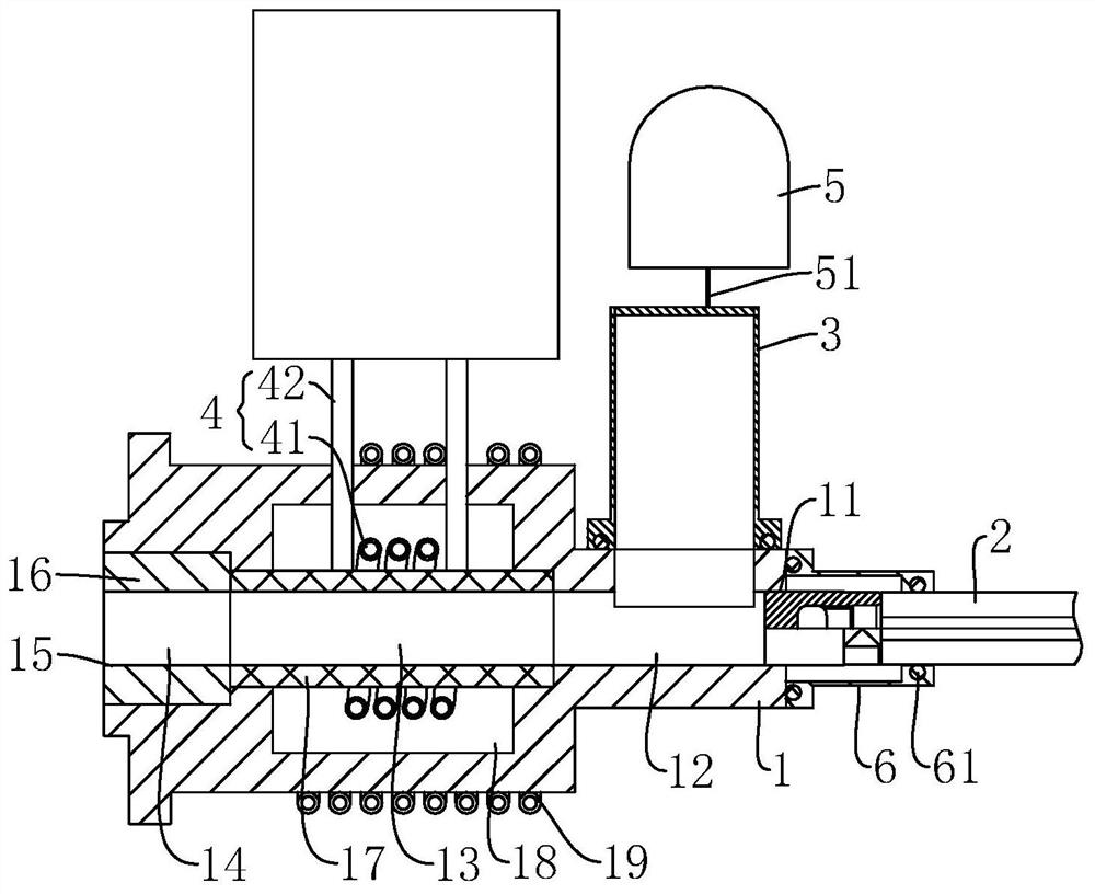
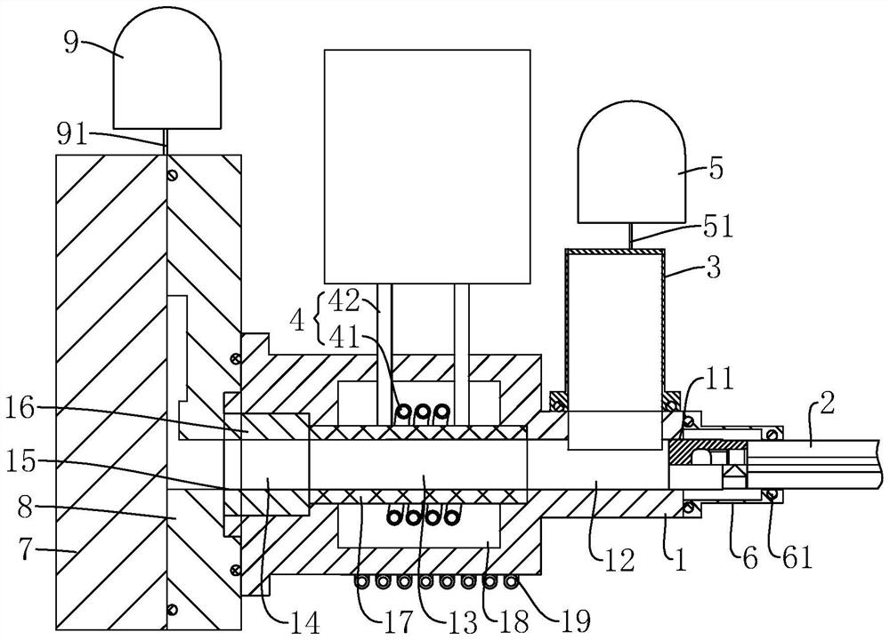
[0033] A material injection device, comprising a injection cylinder 1, a material pushing hammer 2, a feeding bin 3 and a heating mechanism 4. The injection cylinder 1 is provided with an inlet 11, a blanking chamber 12, a heating cavity 13, injection cavity 14 and outlet 15, specifically, injection cylinder 1 is arranged horizontally, inlet 11 and outlet 15 are respectively located at both ends of injection cylinder 1; pusher hammer 2 is slidably connected to inlet 11, pusher hammer 2 has a pushing end, which moves along the axial direction of the injection cylinder 1, and the pushing end can push the material to move from the blanking chamber 12 to the heating chamber 13, the injection chamber 14 and the outlet 15, and then to the blanking chamber 12, specifically, the end of the pusher hammer 2 away from the pusher end can be connected to a power source, and the power source pushes the pusher hammer 2 to move along the axis of the injection cylinder 1; the feed bin 3 is connect


PUM


Abstract

The invention discloses an injection device, a die-casting machine and a die-casting method. Taking one as an example, the injection device comprises an injection barrel, a material pushing hammer, a feeding bin and a heating mechanism; an inlet, a falling material cavity, a heating cavity, an injection cavity and an outlet which communicate with one another are sequentially formed in the injection barrel in the axis direction of the injection barrel; the material pushing hammer is slidably connected to the inlet, the material pushing hammer is provided with a material pushing end, the material pushing end moves in the axis direction of the injection barrel, and the material pushing end can push materials to move to the heating cavity, the injection cavity and the outlet from the material falling cavity; the feeding bin is connected to the injection barrel, and the feeding bin is in communication with the falling material cavity; and the heating mechanism is connected to the injection barrel and surrounds the heating cavity. According to the device, heating and material injection are completed in the injection barrel, a conveying path of molten materials is short, and the molten materials are always in a lightly sealed state, such that the material oxidation condition is greatly reduced; and due to the fact that the conveying path is short, heat loss is relatively small during material conveying, the temperature difference is relatively small, and the quality of finished products is relatively good.

Description


Claims


Application Information

Patent Timeline
Owner YAN HING MACHINERY FOSHAN CO LTD
Why Eureka
Try Eureka