Wastewater treatment device with stirring structure
A wastewater treatment and aeration device technology, applied in mixers with rotating stirring devices, water/sewage treatment, biological water/sewage treatment, etc., can solve the problem that bacteria and more solid impurities cannot be removed and cannot meet the requirements of electroplating Efficient sewage treatment needs, poor stability of organic matter removal, etc., to avoid clogging, meet usage needs, and reduce pollution
- Summary
- Abstract
- Description
- Claims
- Application Information
AI Technical Summary
Benefits of technology
Problems solved by technology
Method used
Image

Examples
Embodiment 1
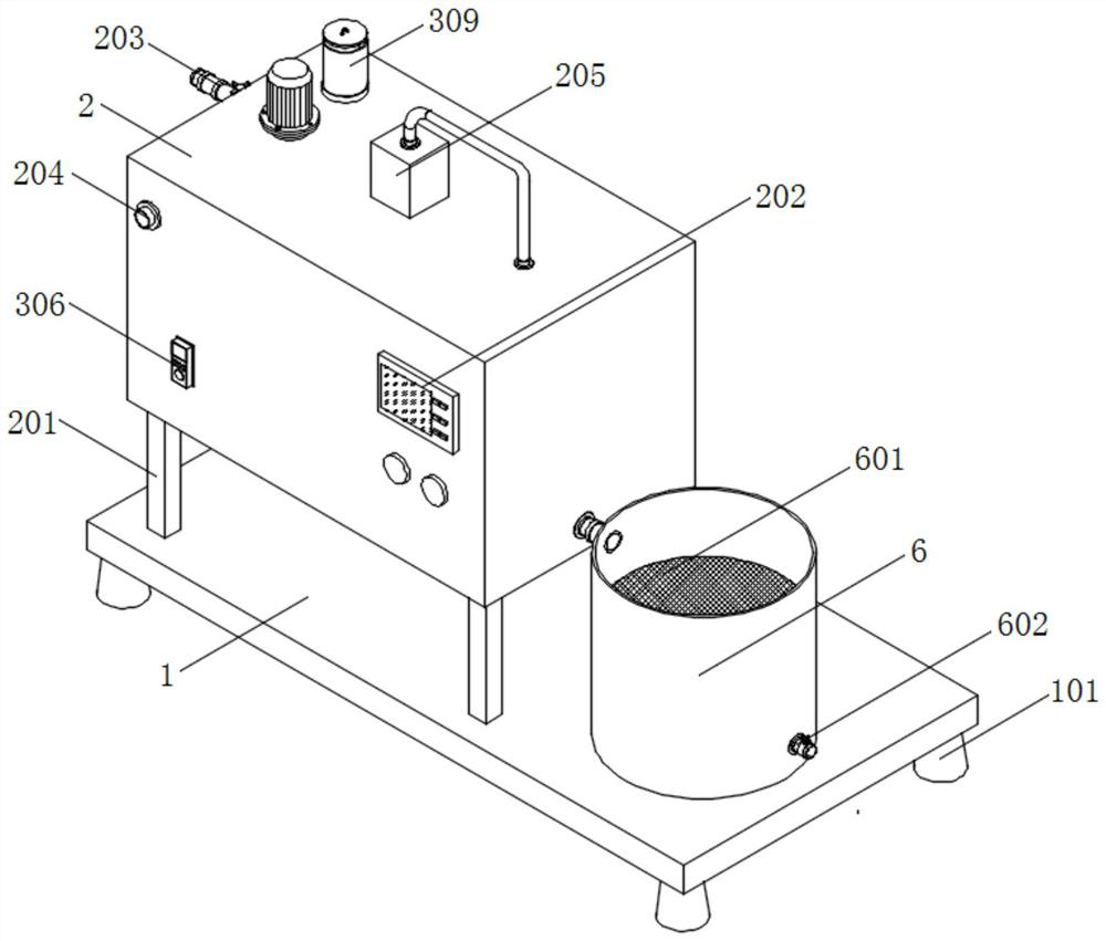
[0028] Embodiment 1, including a base 1, a device body 2 and a pillar 201, the bottom of the base 1 is equipped with a foot 101, the top of the base 1 is installed with a device body 2, the bottom of the device body 2 is equipped with a pillar 201, and the bottom of the pillar 201 Connected to the top of the base 1, a control panel 202 is installed on the front of the device body 2, a waste water pipe 203 is installed on one side of the device body 2, a float outlet 204 is installed on the front of the device body 2, and the center of the top of the device body 2 is installed There is an installation box 205, and the legs 101 support the wastewater treatment device. The pillar 201 supports the device body 2 and makes the discharge of flocculated dirt more convenient, which is convenient for the staff to recycle and process. The operating speed of the motor 301 is adjusted through the control panel 202. The automatic input of the flocculant reduces the labor intensity of the staff
Embodiment 2
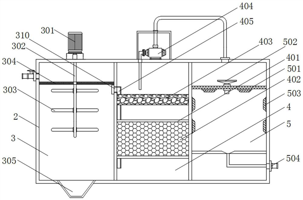
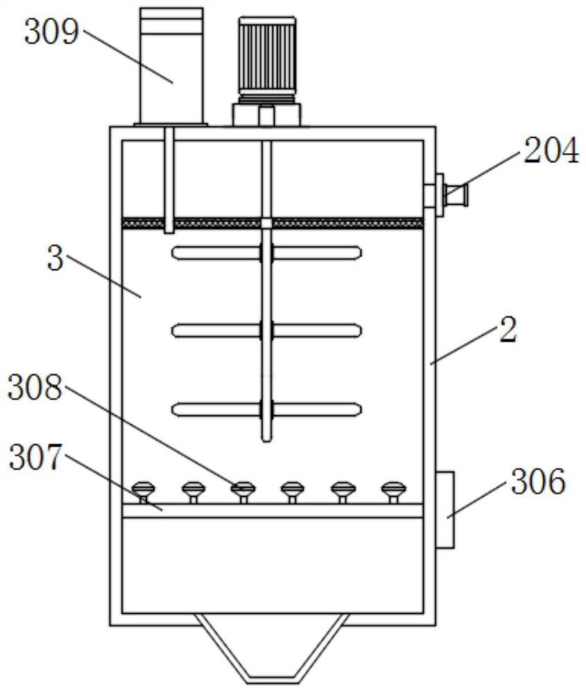
[0030]Embodiment two, comprising device body 2, flocculation tank 3 and filter tank 4, the inside of device body 2 is equipped with flocculation tank 3, and the top of device body 2 is equipped with motor 301, and motor 301 is positioned at the side of installation box 205, and motor The output end of 301 runs through the top of the flocculation tank 3, and a rotating rod 302 is installed on the outside of the rotating rod 302. A stirring blade 303 is installed on the outside of the rotating rod 302. A grid 304 is installed on the inner wall of the flocculation tank 3. The bottom of the flocculation tank 3 is provided with a sewage outlet 305. , the front of the device body 2 is equipped with an aeration device 306, and the aeration device 306 is located below the float outlet 204, and the output end of the aeration device 306 is installed with an exhaust pipe 307 through the front of the device body 2, and the exhaust pipe 307 is located in the inside of the flocculation tank 3,
Embodiment 3
[0032] Embodiment three, comprising device body 2, disinfection tank 5 and water storage tank 6, the inside of device body 2 is equipped with disinfection tank 5, and disinfection tank 5 is positioned at the other side of filtration tank 4, and the inner wall of disinfection tank 5 is installed with Partition 501, the top center position of partition 501 is equipped with water inlet bucket 502, and disinfection lamp 503 is installed on the inner wall of both sides of disinfection pond 5, and drainpipe 504 is installed on the other side of device body 2, and the drainpipe 504 The input end is connected to the interior of the disinfection tank 5, the disinfection tank 5 provides an installation position for the partition 501, the water inlet 502 can control the water volume, and the disinfection lamp 503 irradiates the waste water to make the disinfection effect of the waste water better. The integrated The treatment device improves the working efficiency of waste water treatment. T
PUM
 Abstract
Description
Claims
Application Information
 - R&D Engineer
- R&D Manager
- IP Professional
- Industry Leading Data Capabilities
- Powerful AI technology
- Patent DNA Extraction
Browse by: Latest US Patents, China's latest patents, Technical Efficacy Thesaurus, Application Domain, Technology Topic.
© 2024 PatSnap. All rights reserved.Legal|Privacy policy|Modern Slavery Act Transparency Statement|Sitemap