Photoelectric dumping switch

A photoelectric switch technology, applied in the field of photoelectric dump switch, can solve the problems of long production cycle, complicated assembly, easy to fall off, etc., and achieve the effect of simple manufacture, convenient packaging and simple structure

Inactive Publication Date: 2022-03-29
常德思高技术有限公司
View PDF1 Cites 0 Cited by
  • Summary
  • Abstract
  • Description
  • Claims
  • Application Information

AI Technical Summary

Benefits of technology

This patented technology allows for easy detection or shut-off of certain lights during operation. It uses an optoelectrodump switch made up of small spheres filled into a container called a bunker assembly. Each sphere has two electrodes - one on its surface and another outside. One end of every cube also contains tiny holes where there's a rod inside. These tubular elements allow water molecules (water) to enter while preventing any particles like dirt or debris entering them. By placing these components face each others correctly, they can detect if something needs attention even before being turned off completely.

Problems solved by technology

This patented technical problem addressed by this patents relates to improving the design and construction of an electronics device for controlling its operation when it needs to be stopped down due to being left unattended on their own. Existing devices have limitations because they can easily tilt them during installation without losing functionality.

Method used


Image

  • Photoelectric dumping switch
  • Photoelectric dumping switch
  • Photoelectric dumping switch

Examples


Embodiment Construction

[0024] In order to make the purpose, technical solution and advantages of the present invention clearer, the present invention will be further described in detail below in conjunction with the accompanying drawings.

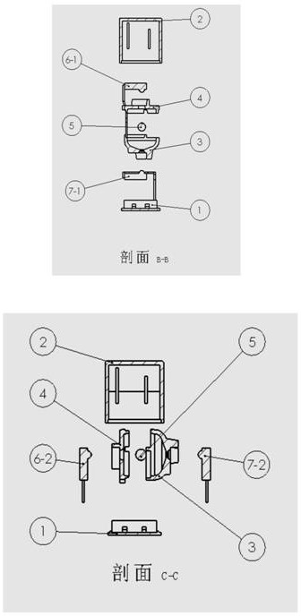
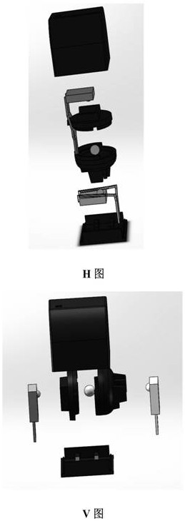
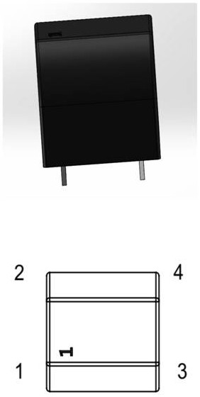
[0025] Such as Figure 1-10 As shown, the present invention provides a photoelectric dump switch, which is characterized by comprising: a housing 2 with an inner cavity, and a vertical ball bin assembly is arranged in the inner cavity of the housing 2, and the ball bin assembly includes a bin body 3 , Canopy cover 4, ball 5, photoelectric emission tube 6-1 and photoelectric receiving tube 7-1, by the ball bin assembly with ball 5, the bottom of ball bin assembly is provided with photoelectric emission tube 6-1, and the top is provided with photoelectric receiving tube 7 -1, and the emitting end cylinder of the photoelectric emitting tube 6-1 and the receiving end cylinder of the photoelectric receiving tube 7-1 are arranged opposite to the center of the ball 5, the


PUM


Abstract

The invention belongs to electronic components, and particularly relates to a photoelectric type dumping switch which comprises a shell with an inner cavity, a ball bin assembly capable of being installed horizontally and vertically is arranged in the inner cavity of the shell, and the ball bin assembly comprises a bin body, a bin cover, a ball, a photoelectric transmitting tube and a photoelectric receiving tube. And a bottom cover for ultrasonic packaging is arranged at the bottom of the shell. A ball bin assembly with a ball is arranged, a photoelectric transmitting tube is arranged at the bottom of the ball bin assembly, a photoelectric receiving tube is arranged at the top of the ball bin assembly, and a transmitting end cylinder of the photoelectric transmitting tube and a receiving end cylinder of the photoelectric receiving tube directly face the center of the ball, the center of a bin body and the center of a bin cover. Due to blocking of the ball, the photoelectric receiving tube cannot receive light rays emitted by the photoelectric transmitting tube; when the toppling switch topples, the ball deviates from the round through hole in the bottom of the bin body and does not block light emitted by the photoelectric transmitting tube any more, so that the light emitted by the photoelectric transmitting tube penetrates through the round through hole of the ball bin assembly and is received by the photoelectric receiving tube, and the photoelectric receiving tube generates corresponding reaction to prompt that the toppling state is at the moment. Ultrasonic welding packaging is used, manufacturing is easy, packaging is convenient, and the structure is simple.

Description


Claims


Application Information

Patent Timeline
Owner 常德思高技术有限公司
Why Eureka
Try Eureka