Automatic switching type condensation labyrinth

An automatic switching and labyrinth technology, which is applied in the direction of steam/steam condenser, lighting and heating equipment, etc., can solve the problems of inconvenient switching and using multiple cooling methods, single cooling method, and inconvenient use, so as to achieve the convenience of air inlet pipe and Air outlet duct, easy to open or close, easy to use

Pending Publication Date: 2022-04-01
东台宣龙防腐管道设备有限公司
View PDF0 Cites 0 Cited by
  • Summary
  • Abstract
  • Description
  • Claims
  • Application Information

AI Technical Summary

Problems solved by technology

[0003] The purpose of the present invention is to provide an automatic switchable condensation labyrinth to solve the problem that the existing cooling labyrinth propos

Method used


Image

  • Automatic switching type condensation labyrinth
  • Automatic switching type condensation labyrinth
  • Automatic switching type condensation labyrinth

Examples


Example Embodiment

[0040] The following will clearly and completely describe the technical solutions in the embodiments of the present invention with reference to the accompanying drawings in the embodiments of the present invention. Obviously, the described embodiments are only some, not all, embodiments of the present invention. Based on the embodiments of the present invention, all other embodiments obtained by persons of ordinary skill in the art without making creative efforts belong to the protection scope of the present invention.

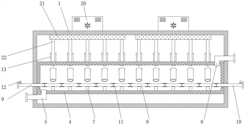
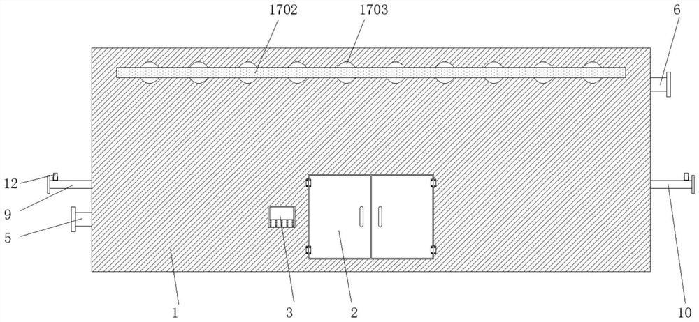
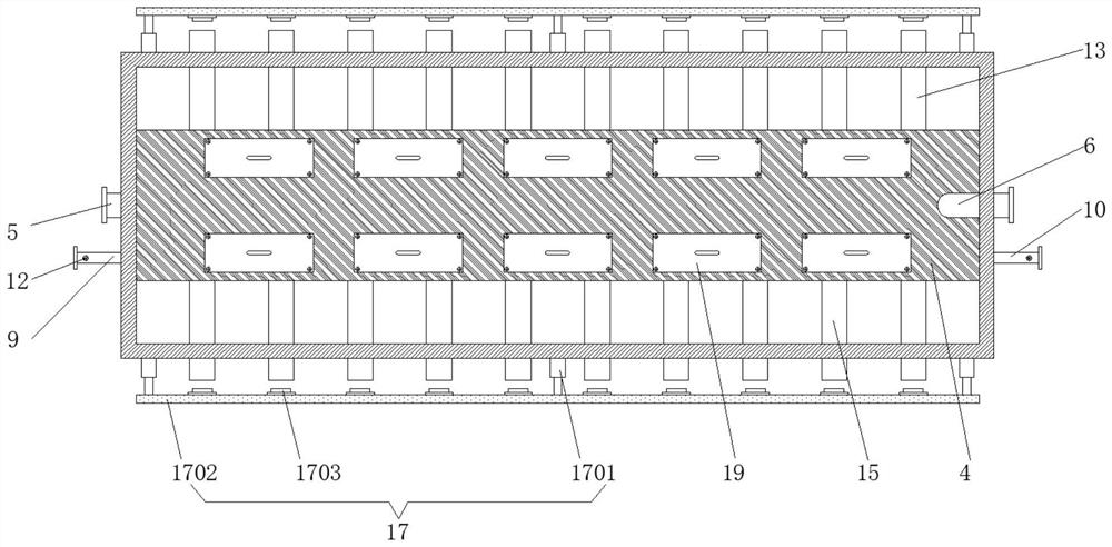
[0041] see Figure 1-6 , the present invention provides a technical solution: automatic switching condensation maze, according to figure 1 and figure 2 As shown, the water outlet channel 5 runs through one side of the thermal insulation outer box 1 and is connected to the bottom of the inner box 4, and the inner box 4 is fixed on the inner side of the thermal insulation outer box 1, and the front end of the thermal insulation outer box 1 is fixed with a control


PUM


Abstract

The automatic switching type condensation labyrinth comprises a water outlet channel, a water inlet channel, an air inlet pipeline, an air outlet pipeline, an air inlet pipeline, an air outlet pipeline, pipeline opening and closing control mechanisms, a manhole and an air cooler, the air outlet pipeline penetrates through the front side of a heat preservation outer box to be connected with an inner box, and the pipeline opening and closing control mechanisms are symmetrically fixed to the two sides of the heat preservation outer box; the air coolers are symmetrically fixed to the two sides of the top of the heat preservation outer box, and the ventilation channels are symmetrically fixed to the two sides of the top in the heat preservation outer box. According to the automatic switching type condensation labyrinth, the pipe plugs can move along with the moving plate in sequence, the air inlet pipeline and the air outlet pipeline can be opened or closed conveniently, and when smoke is subjected to condensation treatment in an air cooling mode, the air inlet pipeline and the air outlet pipeline need to be opened; when an air cooling mode is not adopted to condense the flue gas, the air inlet pipeline and the air outlet pipeline need to be opened, and the device can be automatically switched and butted in a water cooling mode, an air cooling mode and a manual cold source mode, so that the device is more convenient to use.

Description


Claims


Application Information

Patent Timeline
Owner 东台宣龙防腐管道设备有限公司
Why Eureka
Try Eureka