Common mode filter and electronic equipment

A common mode filter, electronic equipment technology, applied in transformer/inductor parts, transformer/inductor coil/winding/connection, circuits, etc., can solve the problems of poor common mode noise filtering effect, etc. Filtering effect, reducing signal loss, small difference in equivalent permeability

Pending Publication Date: 2022-04-08
SHENZHEN SUNLORD ELECTRONICS
View PDF0 Cites 0 Cited by
  • Summary
  • Abstract
  • Description
  • Claims
  • Application Information

AI Technical Summary

Benefits of technology

This patented technology allows for improved filtration by creating multiple parallel conductive paths through an insulating material called the substrate or base plate used during manufacturing processes. By having these different types of wires at opposite ends of one circuit board (the secondary) along its entire length, it becomes possible to achieve better performance without adding extra components like inductors or capacitors.

Problems solved by technology

This patented technical problem addressed by this patents relates to improving image processing systems for transmitting high definition (HD) videos over wireless networks due to increased demand for faster communication speeds along with greater amounts of data transfer rates. However, current methods have limitations when used at these frequencies because they result in reduced signal clarity or distortion caused by unwanted electrical effects like stray capacitance near certain points within the circuit board structure.

Method used


Image

  • Common mode filter and electronic equipment
  • Common mode filter and electronic equipment
  • Common mode filter and electronic equipment

Examples


Embodiment Construction

[0019] In order to make the purpose, technical solution and advantages of the present application clearer, the technical solution of the present application will be clearly described below in conjunction with specific embodiments and corresponding drawings. Apparently, the embodiments described below are only some of the embodiments of the present application, but not all of them. In the case of no conflict, the following embodiments and technical features thereof can be combined with each other, and also belong to the technical solution of the present application.

[0020] It should be understood that in the description of the embodiments of the present application, the terms "center", "longitudinal", "transverse", "length", "width", "thickness", "upper", "lower", "front", " Orientation indicated by rear, left, right, vertical, horizontal, top, bottom, inside, outside, clockwise, counterclockwise, etc. The positional relationship is based on the orientation or positional relati


PUM

PropertyMeasurementUnit
Line widthaaaaaaaaaa
Thicknessaaaaaaaaaa

Abstract

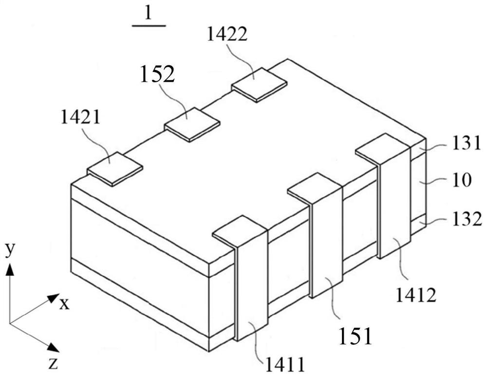
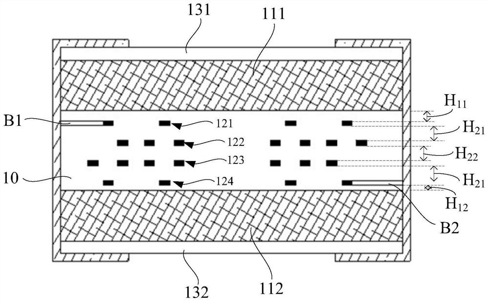
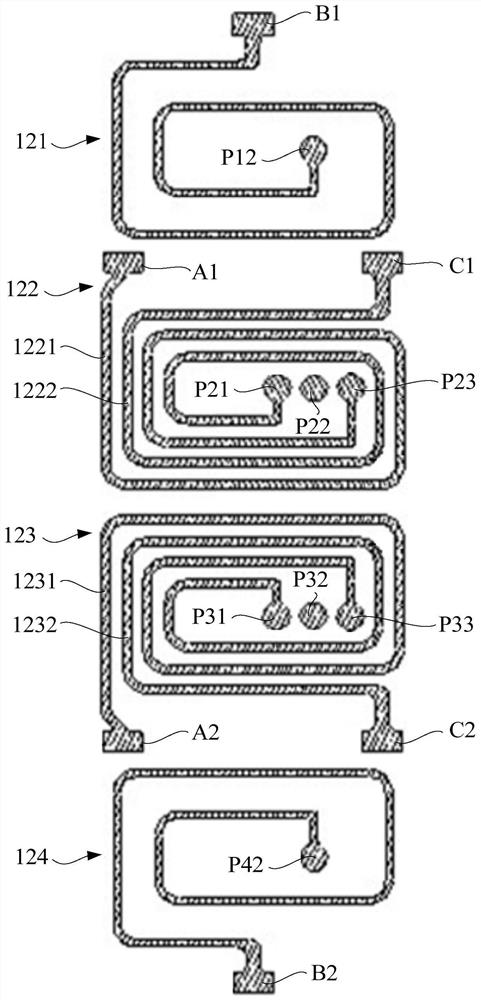
The invention discloses a common mode filter and electronic equipment. The common-mode filter comprises a dielectric layer, and a first magnetic layer, a first electrode layer, a second electrode layer, a third electrode layer, a fourth electrode layer and a second magnetic layer which are stacked in sequence. Every two adjacent layers are isolated through a dielectric layer; the second electrode layer comprises a first sub-coil and a second sub-coil which are insulated, and the two coils surround in the same direction and are electrically connected with the input electrode on the first side; the third electrode layer comprises a third sub-coil and a fourth sub-coil which are insulated, the two coils surround in the same direction and are electrically connected with the output electrode on the second side, the third sub-coil is electrically connected with the first sub-coil, and the fourth sub-coil is electrically connected with the second sub-coil; the second side and the first side are oppositely arranged; the first electrode layer is electrically connected with the fourth electrode layer. According to the invention, the filtering effect of common-mode noise can be improved, and the signal loss can be reduced.

Description


Claims


Application Information

Patent Timeline
Owner SHENZHEN SUNLORD ELECTRONICS
Why Eureka
Try Eureka