Accelerating tube for linear accelerator and linear accelerator

A linear accelerator and accelerating tube technology, applied in linear accelerators, pharmaceutical equipment, and other medical equipment, can solve problems such as low cooling efficiency, poor heat dissipation effect, and high temperature in local areas, and achieve the effect of heat elimination

Pending Publication Date: 2022-04-19
QINGDAO CENT HOSPITAL
View PDF0 Cites 0 Cited by
  • Summary
  • Abstract
  • Description
  • Claims
  • Application Information

AI Technical Summary

Problems solved by technology

And because the inner cavity of the accelerating tube is in a vacuum environment, the heat dissipation effect is poor, so the temperature in the local area is often too high, which affects its stability
At present, the entire system is usually cooled by a water cooling system, and there is no cooling device specially set up for the s

Method used

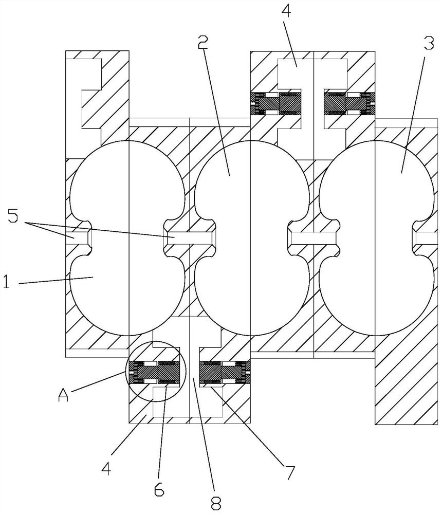
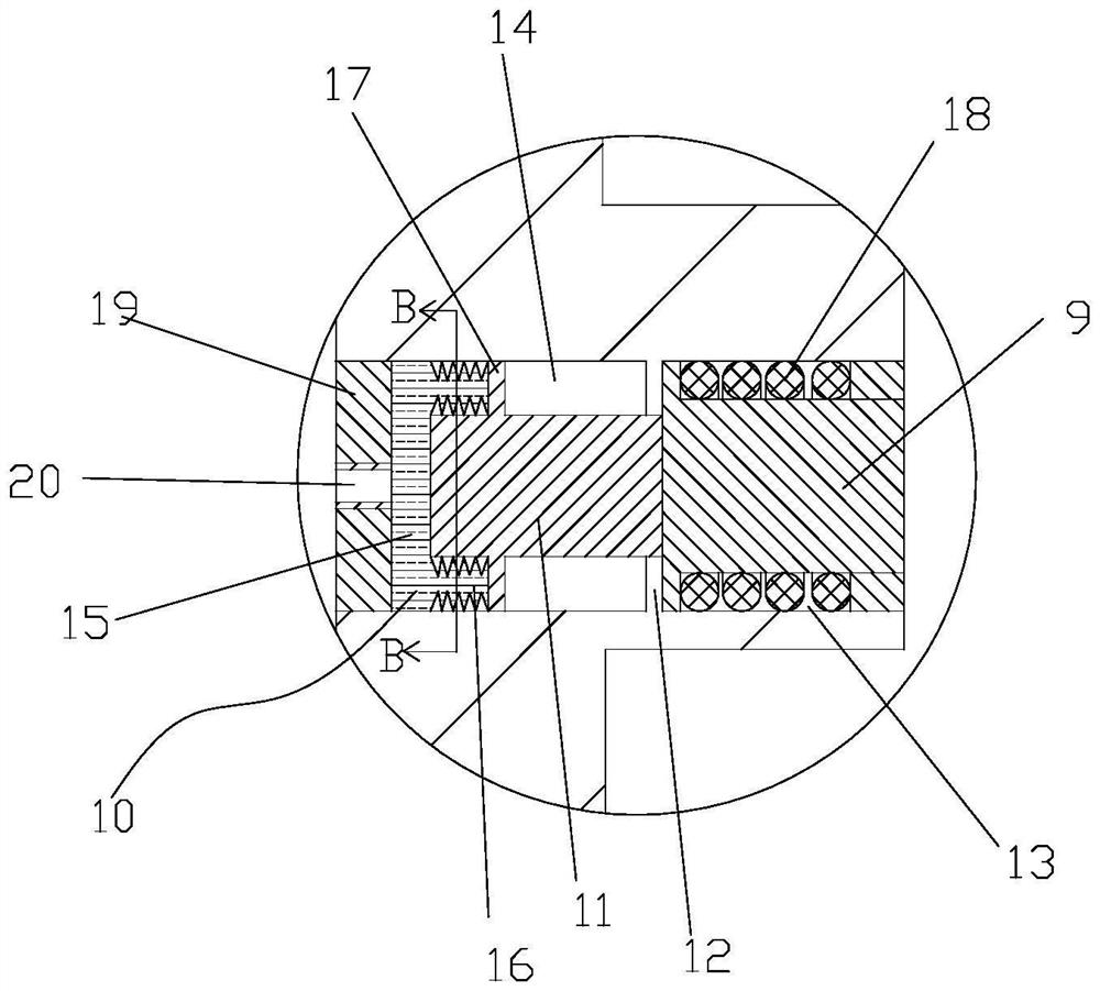
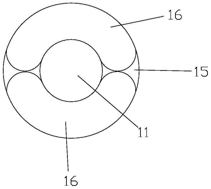

Image

  • Accelerating tube for linear accelerator and linear accelerator
  • Accelerating tube for linear accelerator and linear accelerator
  • Accelerating tube for linear accelerator and linear accelerator

Examples


Embodiment Construction

[0030] The technical solutions in the embodiments of the present invention will be clearly and completely described below in conjunction with the drawings in the embodiments of the present invention. Obviously, the described embodiments are only part of the embodiments of the present invention, not all of them. Based on the embodiments of the present invention, all other embodiments obtained by persons of ordinary skill in the art without making creative efforts fall within the protection scope of the present invention.

[0031] It should be noted that all directional indications (such as up, down, left, right, front, back...) in the embodiments of the present invention are only used to explain the relative relationship between the various components in a certain posture (as shown in the accompanying drawings). When the positional relationship, movement conditions, etc., if the specific posture changes, the directional indication will also change accordingly.

[0032] In addition


PUM


Abstract

Cooling liquid flows into an annular cooling cavity formed in a sleeve from a first liquid inlet channel of a first end cover, then flows into a second liquid outlet channel of a second end cover through the annular cooling cavity, and then flows into a cooling pipe arranged outside the sleeve through the second liquid outlet channel; the cooling liquid finally flows back to the first liquid outlet channel of the first end cover through the cooling pipe, so that the cooling liquid forms circulating backflow; the cooling liquid flowing through the annular cooling cavity can take away heat in the accelerating pipe, and the cooling liquid with the heat in the accelerating pipe is cooled in the external cooling pipe, so that most of the heat is eliminated through the structural arrangement of the cooling device.

Description


Claims


Application Information

Patent Timeline
Owner QINGDAO CENT HOSPITAL
Why Eureka
Try Eureka