Heat recovery system of hybrid electric vehicle

A technology of hybrid electric vehicles and heat recovery, applied in electric vehicles, vehicle energy storage, vehicle components, etc., can solve the problems of battery life and durability decline, and achieve the effect of improving vehicle safety factor, low cost, and fewer parts

Inactive Publication Date: 2020-08-07
ZHEJIANG GEELY HLDG GRP CO LTD +1
View PDF6 Cites 0 Cited by
  • Summary
  • Abstract
  • Description
  • Claims
  • Application Information

AI Technical Summary

Benefits of technology

This patented technology helps reduce fuel consumption by utilizing an internal combustion engine with its own waste heat source (heat) that powers one or more components like this device's condenser). By reusing these exhaust gases from another part called the generator, less expensive equipment becomes available at lower costs compared to traditional methods. Additionally, there are other systems used inside the cabin where passengers use their batteries during winter months when they want warm up again later on - including those related to temperature control and power supply issues. Overall, this innovation improves overall performance and reduces environmental impact while reducing fuel usage.

Problems solved by technology

This patented technical problem addressed in this patents relates to providing a better solution for efficiently managing the coolant used on hybrid electrical cars while maintain their performance over time without compromised reliance upon external resources like refrigerators.

Method used


Image

  • Heat recovery system of hybrid electric vehicle
  • Heat recovery system of hybrid electric vehicle
  • Heat recovery system of hybrid electric vehicle

Examples


Embodiment Construction

[0036] Embodiments of the present invention are described in detail below, examples of which are shown in the drawings, wherein the same or similar reference numerals designate the same or similar elements or elements having the same or similar functions throughout. The embodiments described below by referring to the figures are exemplary and are intended to explain the present invention and should not be construed as limiting the present invention.

[0037] In the description of the present invention, it should be understood that the orientations or positional relationships indicated by the terms "upper", "lower", "top", "bottom", "inner" and "outer" are based on those shown in the accompanying drawings. Orientation or positional relationship is only for the convenience of describing the present invention and simplifying the description, and does not indicate or imply that the referred device or element must have a specific orientation, be constructed and operated in a specific o


PUM


Abstract

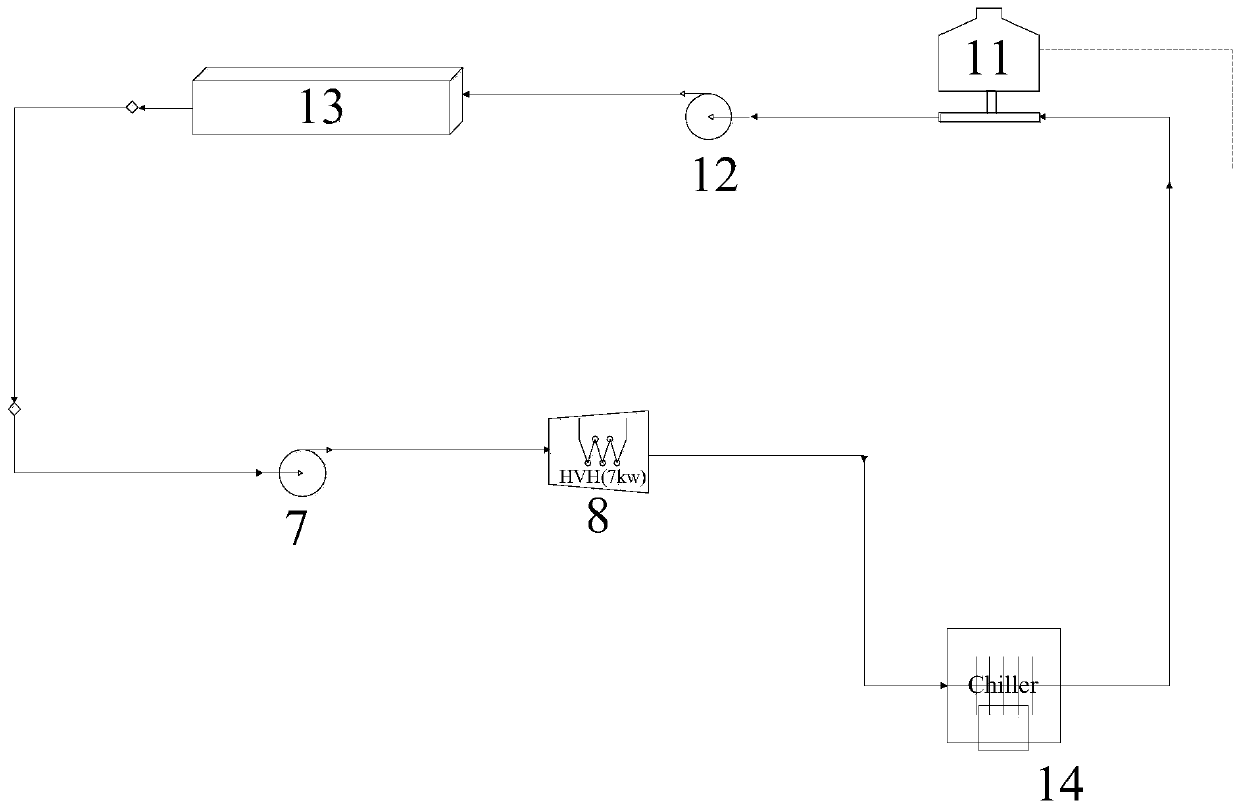
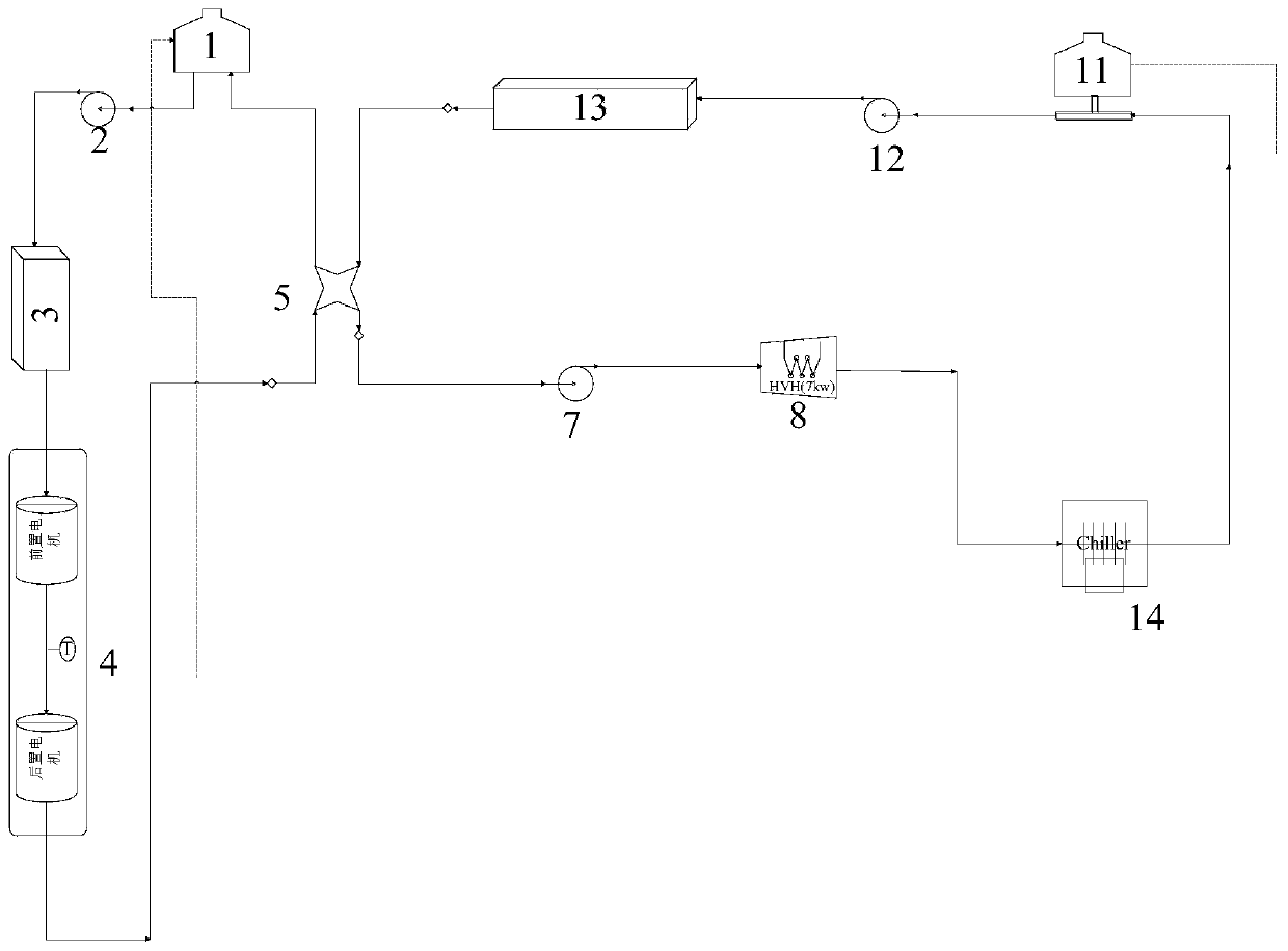
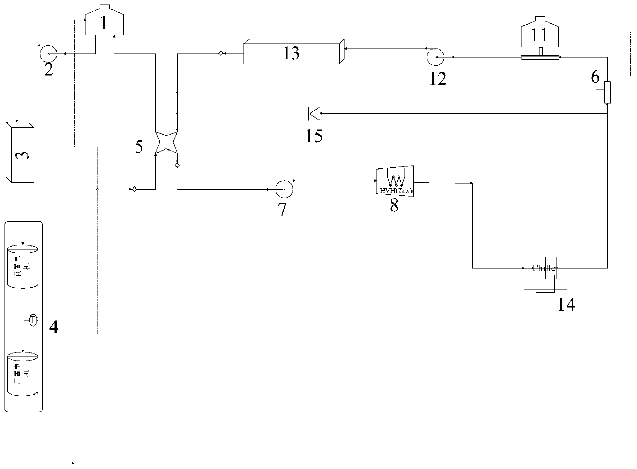
The invention discloses a heat recovery system of a hybrid electric vehicle which comprises a heat recovery loop, and the heat recovery loop comprises a second water pump, a heater, a cooler, a secondexpansion kettle, a third water pump, a battery pack and a second water pump which are sequentially connected through a cooling liquid pipeline. The number of used parts is small, the cost is low, meanwhile, heat of the battery pack can be recovered, the function of heating the battery when the temperature of the battery is too low is achieved, and the energy utilization efficiency is improved.

Description


Claims


Application Information

Patent Timeline
Owner ZHEJIANG GEELY HLDG GRP CO LTD
Why Eureka
Try Eureka