Reaction disc and reagent disc combined device

A combination device and reaction plate technology, which is applied in the field of medical equipment and chemiluminescence immunoassay analyzers, can solve the problems of low detection efficiency, large space occupation, and complex structure, and achieve the effects of high detection efficiency, increased speed, and compact structure

Pending Publication Date: 2022-05-13
苏州立禾生物医学工程有限公司
View PDF0 Cites 0 Cited by
  • Summary
  • Abstract
  • Description
  • Claims
  • Application Information

AI Technical Summary

Benefits of technology

This technology allows for faster and easier handling when inject liquids or gases through miniature test tubes without having them stick out from their original position during testing due to gravity flow caused by gravity's force on the tube walls. It also improves accuracy because it uses special structures inside the reactors instead of just one large cup filled with water. Overall, this new method simplifies the way experiments take place while ensuring accurate results.

Problems solved by technology

This patented technical problem addressed in this patents relates to improving the performance and functionality of chemical analysis instruments due to their size limitations and limited capacity. Current methods involve adding multiple components like lamps, filters, mixer tubings, light sources, detectors, magnets, etc., leading to increased costs associated with each component separately.

Method used


Image

  • Reaction disc and reagent disc combined device
  • Reaction disc and reagent disc combined device
  • Reaction disc and reagent disc combined device

Examples


Embodiment

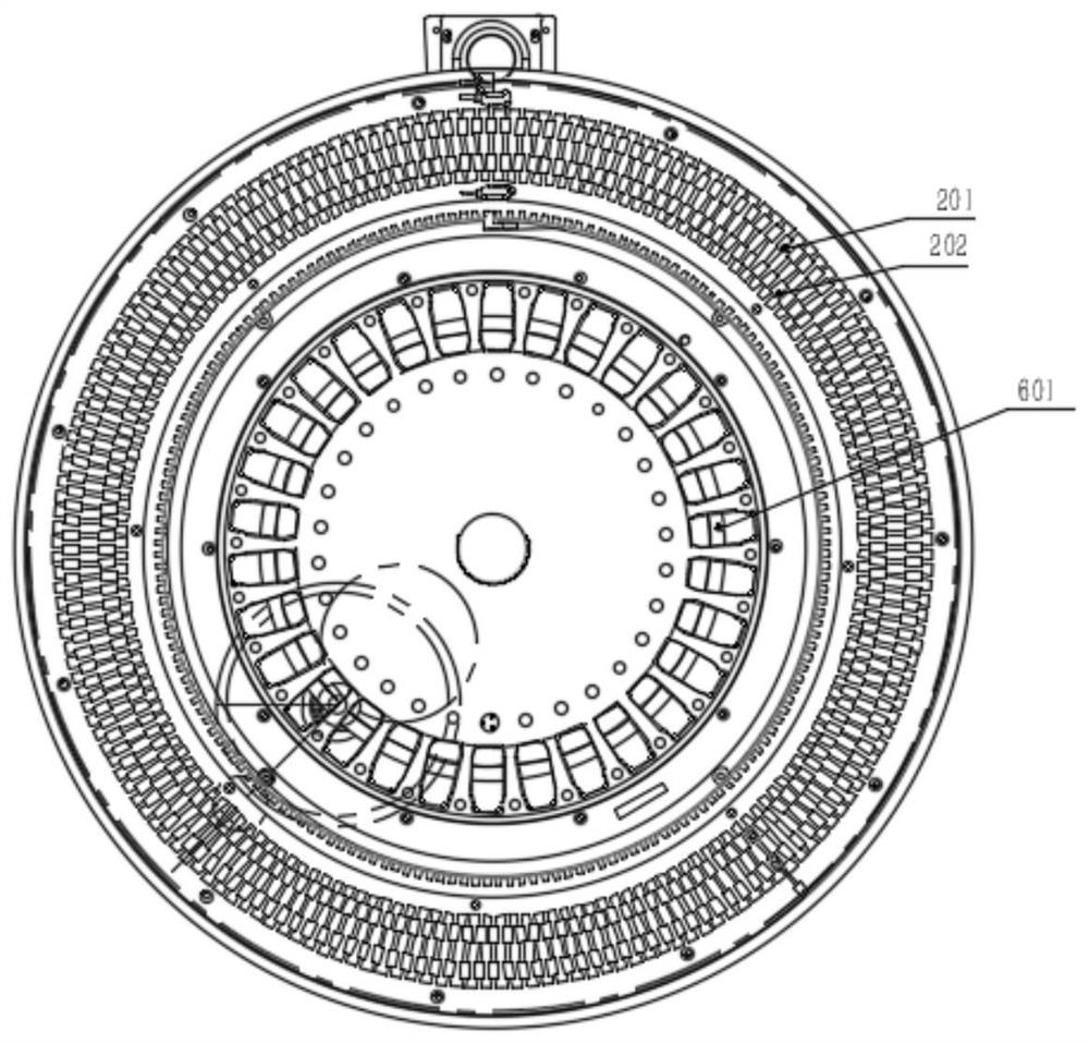
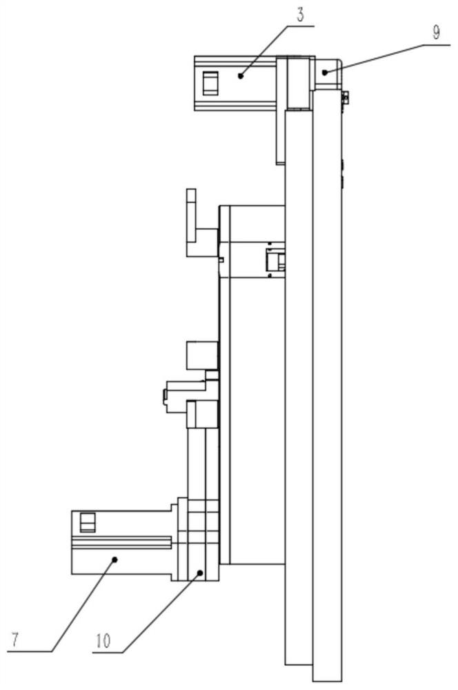
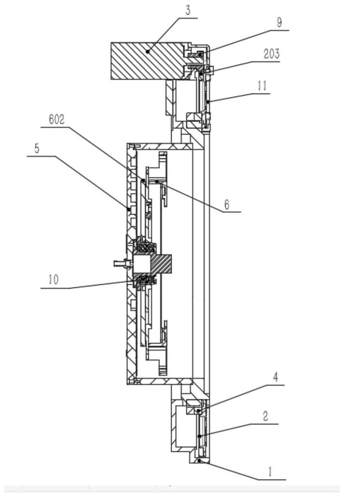
[0039] This embodiment provides a combination device of reaction tray and reagent tray, such as figure 1 , figure 2 and image 3 As shown, including: reaction disk 1, reaction disk rotating plate 2, reaction disk motor 3, reaction disk bearing 4, reagent disk 5, reagent rack 6, reagent disk motor 7, reagent disk bearing 8, gear set A 9, gear set B10, reaction tray cover plate 11; reaction tray rotating plate 2 is provided with outer ring reaction cup groove 201, inner ring reaction cup groove 202 and gear tooth X 203, and reagent rack 6 is provided with reagent cup groove 601 and gear tooth Y 602 ;

[0040] Wherein, the reaction disk motor 3 is fixedly installed on the reaction disk 1, the reaction disk rotating plate 2 and the reaction disk bearing 4 are located in the reaction disk 1, the inner ring of the reaction disk bearing 4 is fixedly installed on the reaction disk 1, and the reaction disk rotating plate 2 It is fixedly connected with the outer ring of the reaction di


PUM


Abstract

The invention relates to a reaction disc and reagent disc combined device which is characterized by comprising a reaction disc assembly and a reagent disc assembly, the reaction disc assembly comprises a reaction disc, a reaction disc rotating plate, a reaction disc motor and a reaction disc bearing; the reagent disc assembly comprises a reagent disc, a reagent frame, a reagent disc motor and a reagent disc bearing; the reaction disc and the reagent disc are designed to be of an integrated structure, the structure is compact, the distance between the reaction disc and the reagent disc is small, the moving distance of the liquid taking needle in the liquid taking and injecting process is shortened, and the liquid taking and injecting speed can be remarkably increased.

Description


Claims


Application Information

Patent Timeline
Owner 苏州立禾生物医学工程有限公司
Why Eureka
Try Eureka