In-situ wire changing device and method for micro electrolytic wire cutting

An electrolytic wire, in-situ technology, applied in accessories, electric processing equipment, electrochemical processing equipment, etc., can solve the problem of time-consuming electrode wire installation, time-consuming electrode wire disassembly, installation and adjustment, and electrode wire diameter easily broken. and other problems to achieve the effect of improving processing efficiency, simplifying the replacement process, and replacing quickly and efficiently.

Pending Publication Date: 2022-05-27
NANJING VOCATIONAL UNIV OF IND TECH
View PDF0 Cites 0 Cited by
  • Summary
  • Abstract
  • Description
  • Claims
  • Application Information

AI Technical Summary

Problems solved by technology

During the installation of the electrode wire, because the diameter of the electrode wire is very small and easy to be broken, the installation of the electrode wire is time-consuming
Therefore, after the electrode wire breaks, the process of dismantling, assembling, and adjusting the electrode wire is very time-consuming, which seriously reduces the processing efficiency of micro-electrolytic wire cutting

Method used


Image

  • In-situ wire changing device and method for micro electrolytic wire cutting
  • In-situ wire changing device and method for micro electrolytic wire cutting
  • In-situ wire changing device and method for micro electrolytic wire cutting

Examples


Example Embodiment

[0025] In order to make the above objects, features and advantages of the present invention more comprehensible, specific implementations of the present invention will be described in detail below in conjunction with the accompanying drawings.

[0026] Secondly, the present invention is described in detail in conjunction with schematic diagrams. When describing the implementation of the present invention in detail, for the convenience of explanation, the cross-sectional view showing the device structure will not be partially enlarged according to the general scale, and the schematic diagram is only an example, and it should not be limited here. The protection scope of the present invention. In addition, the three-dimensional space dimensions of length, width and depth should be included in actual production.

[0027] In order to make the purpose, technical solution and advantages of the present invention clearer, the following will further describe the implementation of the prese


PUM


Abstract

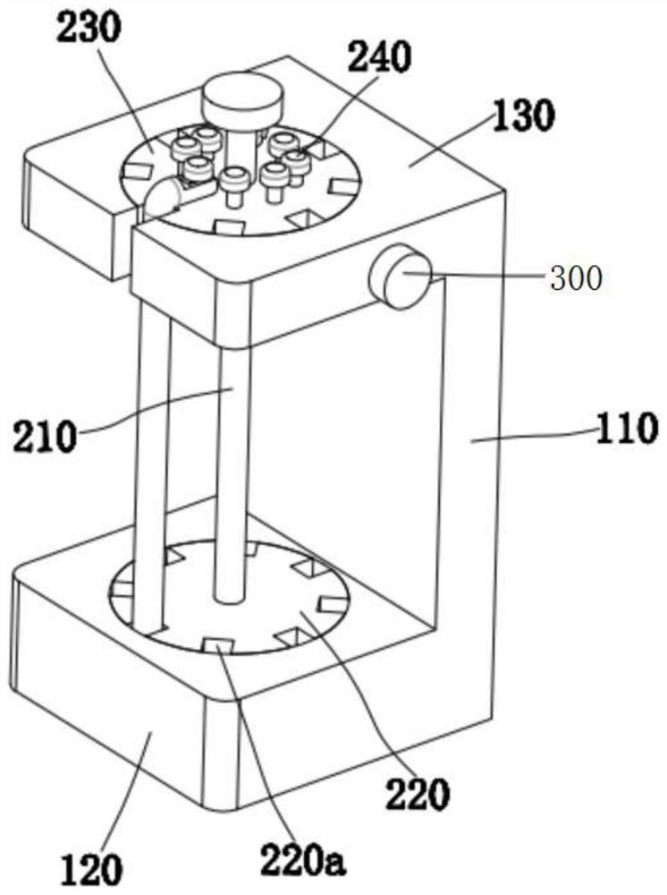
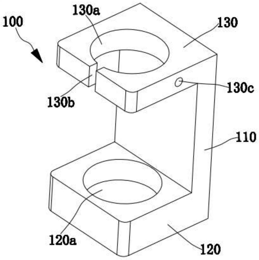
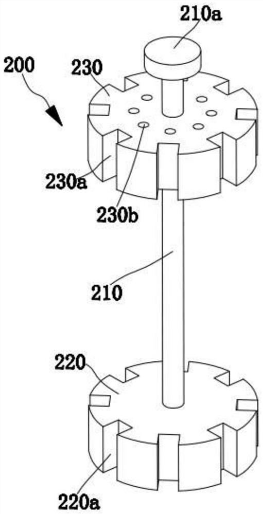
The in-situ wire changing device comprises a supporting seat and a rotary wire changing assembly, the supporting seat comprises a connecting side plate, a base vertically arranged at the bottom of the connecting side plate and a top seat vertically arranged at the top of the connecting side plate, an annular groove is formed in the top of the base, and a through annular groove is formed in the top of the top seat; a first notch communicated with the annular groove is formed in the side edge of the rotary wire changing assembly, and the rotary wire changing assembly comprises a rotary shaft, a first disc arranged at the bottom end of the rotary shaft and located in the annular groove and a second disc arranged at the top end of the rotary shaft and located in the annular groove; the in-situ wire changing device comprises a first disc and a second disc, the side wall of the first disc is provided with second notches distributed in an annular mode, the side wall of the second disc is provided with third notches distributed in an annular mode and aligned with the second notches in a one-to-one mode, and according to the in-situ wire changing device and method for micro-electrolysis wire cutting, after an electrode wire is broken, the electrode wire can be quickly and conveniently changed; and the machining efficiency of micro electrolytic wire cutting is improved.

Description


Claims


Application Information

Patent Timeline
Owner NANJING VOCATIONAL UNIV OF IND TECH
Why Eureka
Try Eureka