Hydroenergy power generation and flow monitoring device based on hollow electrode structure
A monitoring device and electrode structure technology, which is applied in the field of hydropower generation and flow monitoring devices, can solve problems such as corrosion, harsh conditions, and short service life, and achieve the effects of prolonging service life, avoiding corrosion, and making full use of it
- Summary
- Abstract
- Description
- Claims
- Application Information
AI Technical Summary
Problems solved by technology
Method used
Image

Examples
Example Embodiment
[0035] Example 1 Preparation of a hydroelectric power generation and flow monitoring device based on a half-covered hollow electrode structure
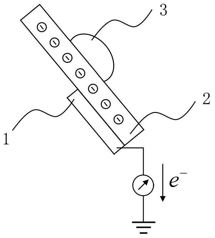
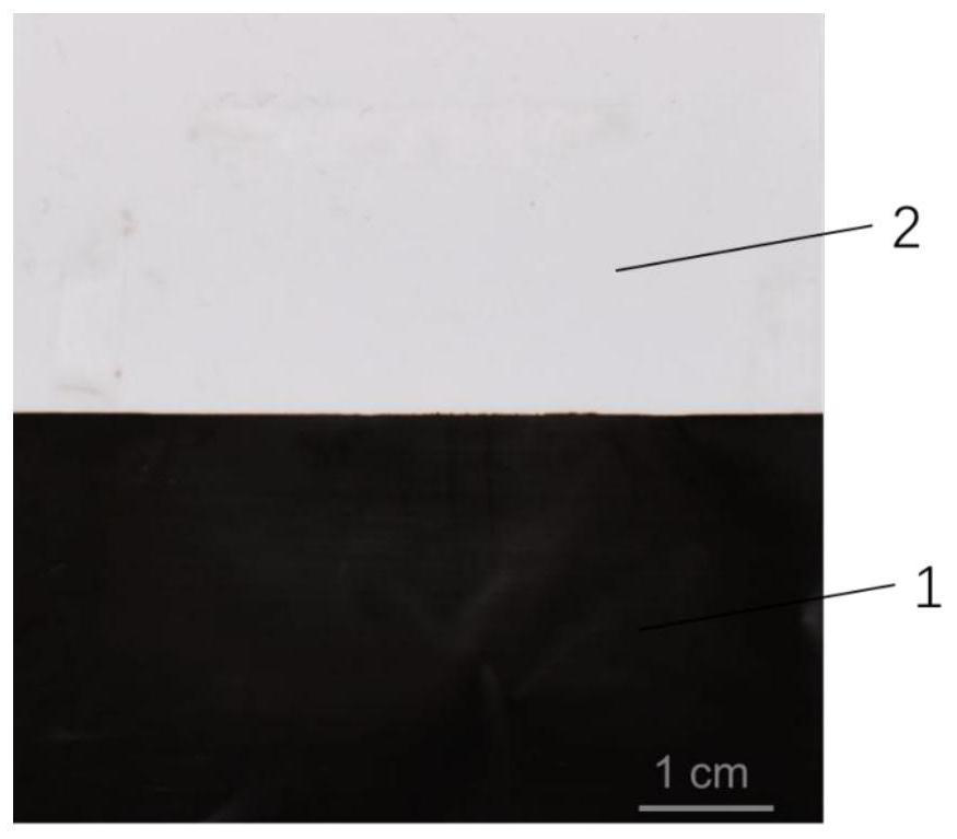
[0036] like figure 1 As shown, a hydroelectric power generation and flow monitoring device based on a hollow electrode structure is composed of an electrode 1, a hydrophobic insulating layer 2, and a liquid source 3; the electrode 1 is fixedly connected to the bottom of the hydrophobic insulating layer 2, and the electrode 1 is not completely The lower surface of the hydrophobic insulating layer 2 is covered to present a "semi-covered hollow" electrode / hydrophobic insulating layer structure. The liquid source 3 is located above the hydrophobic insulating layer 2 , and the liquid in the liquid source 3 can be in contact with the upper surface of the hydrophobic insulating layer 2 and cause relative movement. In this embodiment, the hydroelectric power generation and flow monitoring device is placed at an inclination of 45° with respect
Example Embodiment
[0044] Example 2
[0045] Figure 5 It is a schematic structural diagram of another hydroelectric power generation and flow monitoring device of the present invention. The device is composed of an electrode 1, a hydrophobic insulating layer 2, and a liquid source 3; 2, the liquid in the liquid source 3 can contact the upper surface of the hydrophobic insulating layer 2 and produce relative motion. In this embodiment, the hydroelectric power generation and flow monitoring device is placed at an inclination of 45° relative to the horizontal plane.
[0046] In the embodiment, the sheet electrode 1 is pasted and fixed on the lower surface of the hydrophobic insulating layer 2 by a conductive aluminum tape (purchased from 3M Company, Item No. 431 aluminum tape) with an array hollow structure. The schematic diagram of the structure of electrode 1 in the experimental group is as follows Image 6 As shown in the figure, the size of a single rectangular conductive aluminum tape unit con
Example Embodiment
[0051] Example 3
[0052] Except that the liquid source 3 (liquid) is the continuous turbulent flow of tap water flowing out of the outlet of the urban indoor faucet (the diameter of the water outlet is about 5 mm, and the average flow velocity of the water flow in this embodiment is about 0.5 m / s), the other parts are the same as the experimental device of this embodiment. The experimental apparatus of Example 2 is the same. In this embodiment, the liquid 3 is obtained by flowing down the tap outlet at a height of about 20 cm above the hydrophobic insulating layer 2 , and then contacts the upper surface of the hydrophobic insulating layer 2 and flows disorderly. The rest of the implementation steps are the same as in Example 2.
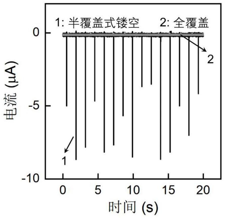
[0053] In this embodiment, a control device in which a conductive aluminum tape (electrode) is completely covered on the lower surface of the hydrophobic insulating layer 2 is also provided.
[0054] The voltage test results of this embodiment are a
PUM
| Property | Measurement | Unit |
|---|---|---|
| Thickness | aaaaa | aaaaa |
| Thickness | aaaaa | aaaaa |
| Resistivity | aaaaa | aaaaa |
Abstract
Description
Claims
Application Information
 - R&D Engineer
- R&D Manager
- IP Professional
- Industry Leading Data Capabilities
- Powerful AI technology
- Patent DNA Extraction
Browse by: Latest US Patents, China's latest patents, Technical Efficacy Thesaurus, Application Domain, Technology Topic.
© 2024 PatSnap. All rights reserved.Legal|Privacy policy|Modern Slavery Act Transparency Statement|Sitemap