Negative inversion structure cause analysis method and system, electronic equipment and storage medium

An analysis method and construction technology, applied in design optimization/simulation, electrical digital data processing, instruments, etc., can solve problems such as lack of research

Pending Publication Date: 2022-06-24
CHINA UNIV OF PETROLEUM (BEIJING)
View PDF0 Cites 0 Cited by
  • Summary
  • Abstract
  • Description
  • Claims
  • Application Information

AI Technical Summary

Benefits of technology

This patented technology helps researchers identify areas where there are positive underground water bodies that may have caused damage or pollution during times they were drilling into them. It also provides data on these damaged regions' appearance over time through analyzing its structure and sediments content. These technical results help explorators better advise future actions related to environmental concerns such as prevention measures like rebuilding roads after construction activities.

Problems solved by technology

This patented technical problem addressed by this patents relates to studying stress corrosion crack initiation caused by lateral pressure during earthquake activity that can lead to damage from tensile failure under repeated loading conditions over time. Existing techniques such as multiple stage simulations may be limited because they only work with one type of material at once (single) rather than two types simultanously like multistage expansions).

Method used


Image

  • Negative inversion structure cause analysis method and system, electronic equipment and storage medium
  • Negative inversion structure cause analysis method and system, electronic equipment and storage medium
  • Negative inversion structure cause analysis method and system, electronic equipment and storage medium

Examples


Embodiment 1

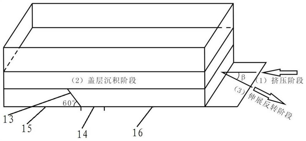
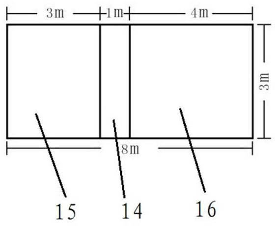
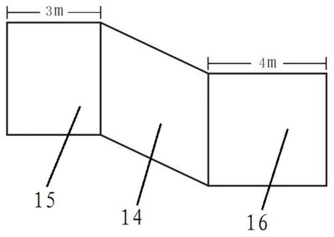
[0052] This embodiment provides a geological generation model, including a stress box, a pre-existing slab fault 13, a deformable base 14, a first rigid base 15, and a second rigid base 16. The pre-existing slab fault and the deformable base 14 , The first rigid base 15 and the second rigid base 16 are connected to each other, and the interior of the box above the base is filled with spherical particles.

[0053] figure 1 It is a schematic structural diagram of a geological generation model disclosed in the present invention, such as figure 1 As shown in the figure, the initial state of the stressed box is set as a cuboid with a length of 8m, a width of 3m and a height of 1m, the box is filled with 166586 spherical particles, and the attribute parameters of the particles are respectively set to porosity 0.15, density 2600.0kg / m 3 , the spherical particle size is 0.03m, and the particle size conforms to the Gaussian distribution. The detailed parameter settings of the geologic

Embodiment 2

[0095] Figure 13 A schematic flowchart of a method for analyzing the causes of negative inversion structures provided by the present invention, such as Figure 13 As shown, the present invention provides a method for analyzing the causes of negative inversion structures, the method comprising:

[0096] S1. Construct a geological generation model of a negative inversion structure, wherein the geological generation model includes two strata separated by a pre-existing plate fault.

[0097] Preexisting slab faults refer to slab faults that pre-exist before the extrusion stage of the negative inversion structure studied in the present invention, which is an important prerequisite for the formation of the negative inversion structure.

[0098] Geological generative model utilizing PFC 3D It is realized by the discrete element numerical simulation technology, quantitatively studies the deformation mechanism of negative inversion structure, and obtains the quantitative data of the ma


PUM

PropertyMeasurementUnit
Densityaaaaaaaaaa
Particle sizeaaaaaaaaaa

Abstract

A negative inversion structure cause analysis method and system, an electronic device, and a storage medium, the method comprising: constructing a geological generation model of a negative inversion structure, the geological generation model comprising two stratums separated by a pre-stored slab fault; the geological generation model is correspondingly controlled sequentially according to an extrusion stage and an extension inversion stage, and the extension angles of the two stratums in the extension inversion stage can be adjusted; recording geometric and kinematic characteristics of the geological generation model at different extension angles in each stage; and acquiring geographic features of a to-be-analyzed region, matching the geographic features with the geometric and kinematic features, judging whether the to-be-analyzed region belongs to a negative inversion structure, and if so, acquiring an extension angle of the to-be-analyzed region in an extension inversion stage. By means of the method, cause analysis can be conducted on the negative reversal basin in the river-side depression, the tectonic deposition appearances of the negative reversal basin in different periods are analyzed, and supplementary suggestions are provided for geological exploration of the basin.

Description


Claims


Application Information

Patent Timeline
Owner CHINA UNIV OF PETROLEUM (BEIJING)
Why Eureka
Try Eureka