Laser film surface coating system

A technology of surface coating and laser film, which is applied to devices and coatings for coating liquids on the surface. Uniform, fully coated effect

Active Publication Date: 2022-07-08
绍兴毅龙镭射科技有限公司
View PDF7 Cites 0 Cited by
  • Summary
  • Abstract
  • Description
  • Claims
  • Application Information

AI Technical Summary

Benefits of technology

This technology allows for two-pass or double-pass printing with an optically clear plastic layer made by applying special coatings onto one side of the sheet material before it goes into production. It achieves this by rotating both sides simultaneously while moving them at different angles along their length. Compensate movements caused by gravity when they are applied over uneven surfaces like curved faces without affecting how well each other works together. Overall, these technical improvements improve the quality and reliability of printed images produced from transparent films such as LCDs (Liquid Crystal Displays).

Problems solved by technology

This patented technical problem addressed in the patant relates to improving the stability and efficiency of applying chemical agents onto surfaces used for printing purposes such as films by creating an improved method of covering them fully when they are being conveyed over long distances without wasteful material usage.

Method used


Image

  • Laser film surface coating system
  • Laser film surface coating system
  • Laser film surface coating system

Examples


Embodiment Construction

[0034] The technical solutions in the embodiments of the present invention will be clearly and completely described below with reference to the accompanying drawings in the embodiments of the present invention. Obviously, the described embodiments are only a part of the embodiments of the present invention, rather than all the embodiments. Based on the embodiments of the present invention, all other embodiments obtained by those of ordinary skill in the art without creative efforts shall fall within the protection scope of the present invention.

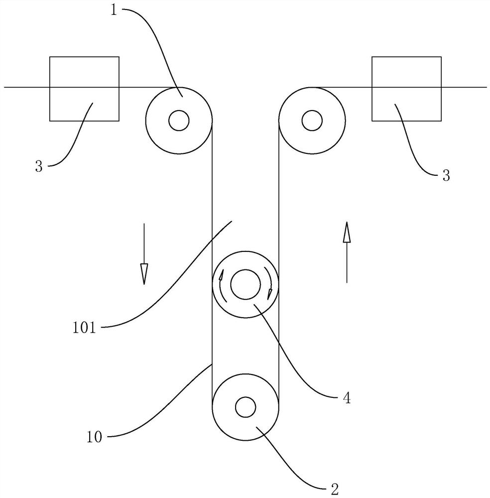
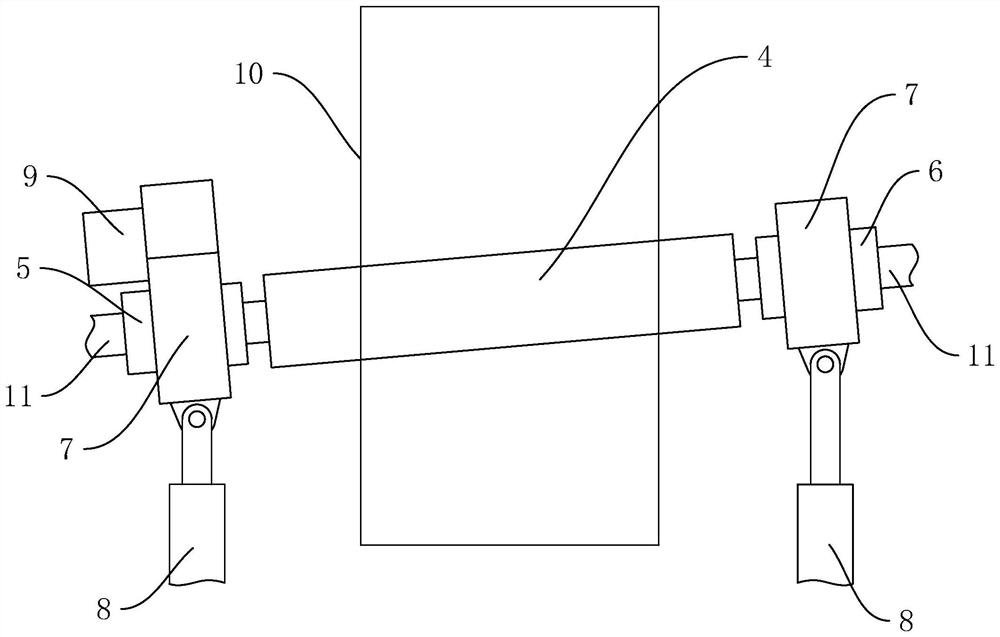
[0035] This embodiment discloses a laser film surface coating system, such as figure 1 , 2 As shown, it includes a coating roller 4 and a guide roller assembly. The guide roller assembly is used to transmit the laser film 10. During the conveying process, the two sides of the laser film 10 pass through the outer circumference of the coating roller 4 and contact each other. The outer peripheries of the cloth rollers 4 are in contact wit


PUM


Abstract

The invention discloses a laser film surface coating system, and relates to laser film production equipment, and the laser film surface coating system is characterized by comprising a coating roller and a guide roller assembly, the guide roller assembly is used for conducting and conveying a laser film, and the two sides of the laser film pass through the periphery of the coating roller and make contact with each other in the conveying process; the rotating direction of the coating roller is opposite to the conveying direction of the laser film; the coating roller is used for coating a laser film at the contact position, and the conveying direction of the coating roller and the laser film is inclined. By adopting a differential rotation mode, the reagent coating efficiency on the surface of the thin film can be improved, and the completeness and uniformity of surface coating are improved.

Description


Claims


Application Information

Patent Timeline
Owner 绍兴毅龙镭射科技有限公司
Why Eureka
Try Eureka