While-drilling azimuth detection data synchronization method and device

A technology of azimuth detection and data synchronization, which is applied in the field of address exploration, can solve problems such as dislocation of azimuth detection, inability to obtain accurate information of strata, and difficulty in realizing synchronous control, etc., and achieve the effect of accurate calculation

Active Publication Date: 2022-07-15
INST OF GEOLOGY & GEOPHYSICS CHINESE ACAD OF SCI
View PDF5 Cites 0 Cited by
  • Summary
  • Abstract
  • Description
  • Claims
  • Application Information

AI Technical Summary

Benefits of technology

This patented technology allows an operator to set up their equipment at different angles during operation without having them adjust themselves manually or wait until they get ready again after each use. It uses timing signals from sensors attached to tools that measure various parameters such as inclination, pressure, temperature, etc., along with other factors like gravity to determine how well these measurements are being done over time. By analyzing this data collected through timings, operators may make informed decisions about optimum placement of steerable instruments within boreholes.

Problems solved by technology

This patented technology solves issues with conventional methods such as measuring depths from boreholes or acquiring 2D image data during drilling operations because they require multiple components (acceleration sensors) separately controlled independently. Additionally, current systems lack precision timing capabilities needed for achieving this purpose.

Method used


Image

  • While-drilling azimuth detection data synchronization method and device
  • While-drilling azimuth detection data synchronization method and device
  • While-drilling azimuth detection data synchronization method and device

Examples


Embodiment Construction

[0031] In order to make the objectives, technical solutions and advantages of the present application clearer, the present invention will be further described in detail below in conjunction with the specific embodiments and with reference to the accompanying drawings. It should be understood that these descriptions are exemplary only and are not intended to limit the scope of the invention. Also, in the following description, descriptions of well-known structures and techniques are omitted to avoid unnecessarily obscuring the concepts of the present invention.

[0032] The accompanying drawings show a schematic structural diagram of an embodiment of the present application. The figures are not to scale and some details may have been omitted for clarity. The various regions, shapes and the relative sizes and positional relationships between them shown in the figures are only exemplary, and in practice, there may be deviations due to manufacturing tolerances or technical limitatio


PUM


Abstract

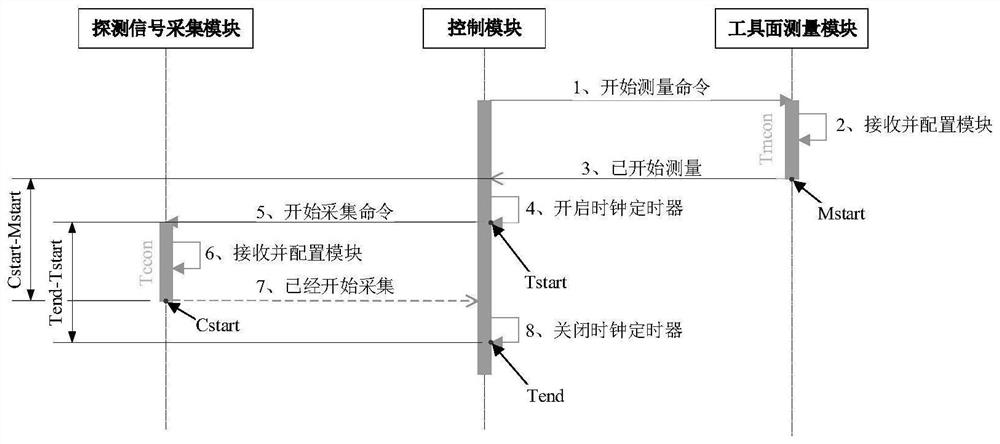
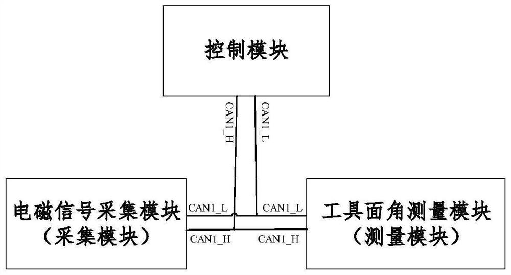
The invention provides a while-drilling azimuth detection data synchronization method and equipment, and the method comprises the steps that a control module starts a timer to record first time according to a measurement starting command sent by a tool face angle measurement module, and sends a detection signal collection starting command to a detection signal collection module; the detection signal acquisition module performs parameter configuration according to the detection signal acquisition starting command, and sends a work starting command to the control module based on a configuration completion state; the control module closes the timer and records second time according to the work starting command; and calculating a deviation angle according to the time difference between the first time and the second time, and correcting the tool face angle measurement module based on the deviation angle.

Description


Claims


Application Information

Patent Timeline
Owner INST OF GEOLOGY & GEOPHYSICS CHINESE ACAD OF SCI
Why Eureka
Try Eureka