Petroleum lifting pump

A lift pump, oil technology, applied in the direction of pumps, jet pumps, non-displacement pumps, etc., can solve the problems of fast heat dissipation, high labor intensity, low efficiency, etc., achieve slow heat dissipation, reduce labor intensity, and improve production. The effect of efficiency

Inactive Publication Date: 2004-12-22
关建华 +1
View PDF0 Cites 3 Cited by
  • Summary
  • Abstract
  • Description
  • Claims
  • Application Information

AI Technical Summary

Benefits of technology

This patented device helps improve the performance of an internal combustion engine used on drilling rigs. It uses steam injecting instead of water injection or gasoline injection, reducing workload while still delivering sufficient torque output. Additionally, its design allows for quicker evacuating of gases without interrupting fluid supply. Overall, these technical improvements enhance the overall effectiveness of the machine's operation.

Problems solved by technology

The technical problem addressed by these inventions relates to improving efficient lifting operations for extracting crude oils (oily substances) while minimizing energy usage compared with traditional methods such as water flooding or chemical techniques that use more expensive materials like surfactants.

Method used


Image

  • Petroleum lifting pump
  • Petroleum lifting pump

Examples


Embodiment Construction

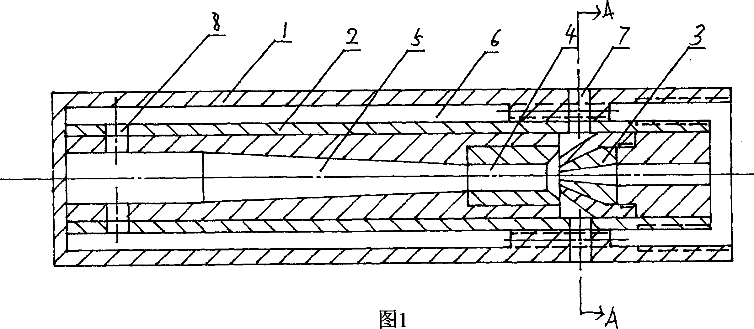
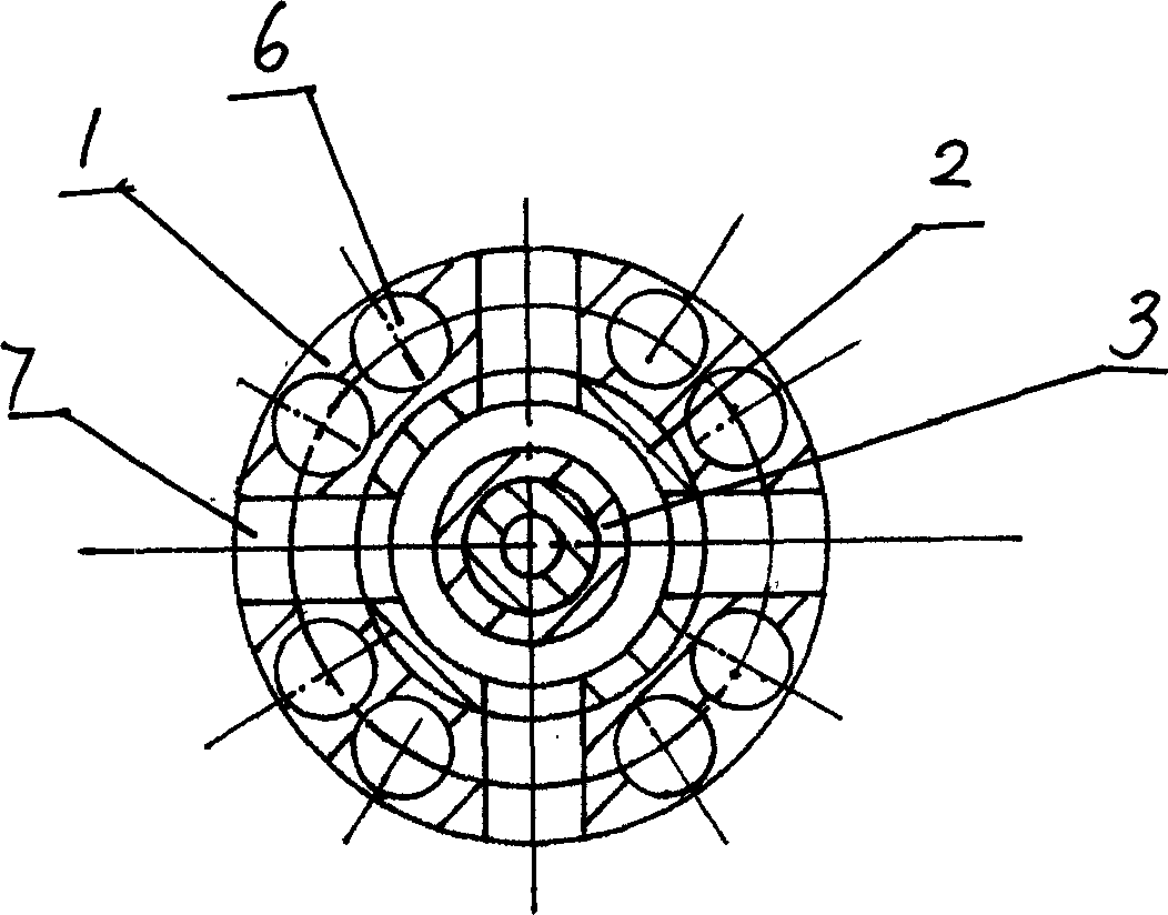
[0010] Figure 1, figure 2 As shown, the petroleum lift pump of the present invention includes an outer pipe 1, the lower end of the outer pipe 1 is a closed end, and the upper end is an open end. The outer pipe 1 is provided with an inner pipe 2, and the wall of the outer pipe 1 is thicker. There are several oil passages 6 on the wall of the outer pipe 1 between the pipes 2, and the nozzle 3, the throat pipe 4 and the diffuser pipe 5 are arranged in the cavity of the inner tube 2 from top to bottom, and the nozzle 3 and the cavity of the inner tube 2 are clamped. Shoulder connection, the nozzle 3 is thus fixed at a certain position in the cavity of the inner tube 2, and there is a gap between the throat 4 and the nozzle 3, when negative pressure is formed at the nozzle 3 in the cavity of the inner tube 2, oil in the oil well enters the throat through the gap The pipe 4 is provided with an oil outlet 8 connected to the lower part of the diffuser pipe 5 and the inner pipe 2. The oi


PUM


Abstract

Lower end of outer tube of the pump is a closed end, and upper end of the outer tube is an open end. Several oil channels are setup between outer tube and inner tube, which is inside the outer tube. Nozzle, jet tube and diffusion tube are inside the inner tube cavity, and there is gap between jet tube and nozzle. Jet tube is connected to diffusion tube. Oil outlet through oil channel connects to inner tube and low part of diffusion tube. There are oil inlets on corresponding position of outer tube, inner tube and nozzle. Features of the pump are: continuous operation with no pause in period of extracting oil, steam going to inner tube so as to save energy, no need of alternative use of two devices so as to reduce labor intensity. The pump is applicable to deep well as well as shallow well.

Description


Claims


Application Information

Patent Timeline
Owner 关建华
Why Eureka
Try Eureka