Light polarizer for display device and its production
A display and polarizing technology, which is applied in optics, instruments, polarizing components, etc., can solve the problems of insignificant improvement of two-side viewing angle, limited improvement of contrast and color saturation, etc.
- Summary
- Abstract
- Description
- Claims
- Application Information
AI Technical Summary
Problems solved by technology
Method used
Image

Examples
Embodiment Construction
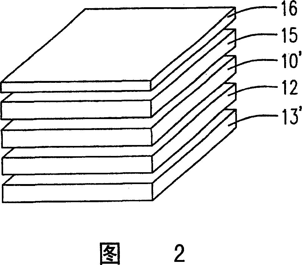
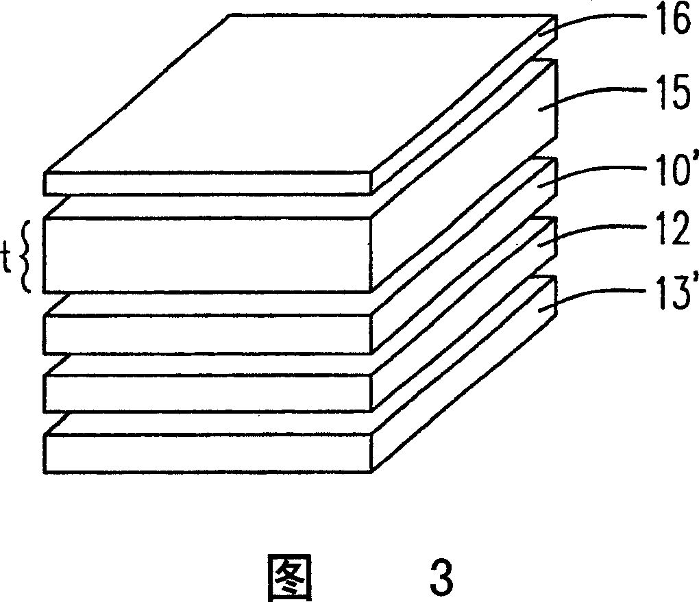
[0019] Please refer to FIG. 2 , which is a schematic diagram of an embodiment of a display with a viewing angle compensation device of the present invention. Wherein a liquid crystal panel 12 is arranged between the upper polarizer 10' and the lower polarizer 13'. In order to solve the problem that the traveling direction of the light caused by the light passing through the polarizing device is too fixed, resulting in too narrow viewing angle, the present invention also sets a viewing angle compensating device on the upper polarizing plate 10', which has a first diffusion layer 15, the first The diffusion layer 15 includes a plurality of particles and fillers, and the original traveling direction is changed from a single direction to multiple directions by light hitting the particles, so as to achieve the effect of viewing angle compensation. The diameter distribution of the particles ranges from several nanometers to tens of microns, and is uniformly distributed.
[0020] The p
PUM
 Abstract
Description
Claims
Application Information
 - R&D Engineer
- R&D Manager
- IP Professional
- Industry Leading Data Capabilities
- Powerful AI technology
- Patent DNA Extraction
Browse by: Latest US Patents, China's latest patents, Technical Efficacy Thesaurus, Application Domain, Technology Topic.
© 2024 PatSnap. All rights reserved.Legal|Privacy policy|Modern Slavery Act Transparency Statement|Sitemap