Anti-poking lock
An anti-pickling and lock head technology, which is applied in the field of pin locks, can solve the problems of being easy to be opened technically by unlocking tools and the poor anti-pickling ability of pin locks, etc., so as to prevent the opening and increase the difficulty
- Summary
- Abstract
- Description
- Claims
- Application Information
AI Technical Summary
Problems solved by technology
Method used
Image

Examples
Example Embodiment
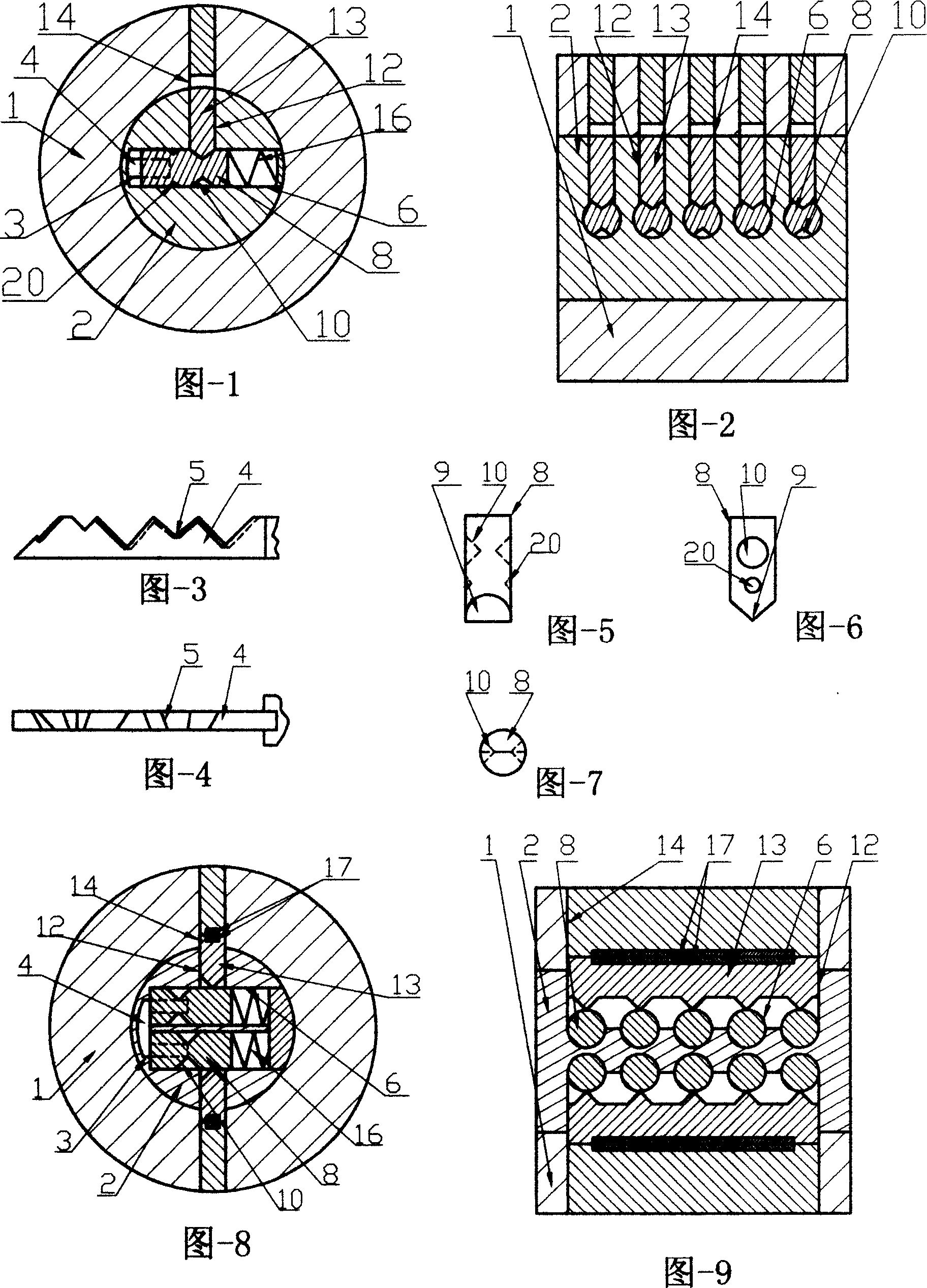
[0038] Embodiment 1: A single-row angle pin anti-spin lock, the structure of which is shown in Figs. 1-7. A rotatable lock core (2) is arranged in the lock head (1), and a key hole (3) in the lock core (2) is communicated with a pin hole (6). A row of pin holes (6) in the lock cylinder (2) communicate with the corresponding round side pin holes (12) and round lock pin pin holes (14) on one side, and each pin hole (6) has An angle marble (8) whose head (9) is in the shape of an axe is matched with the oblique teeth (5) of the key (4). Each angle marble (8) has a pair of side walls at different heights and angular positions. A spring (16) is arranged behind the ball (8) of each angle on the opposite round pit notch (10). Each circular side pin hole (12) has a cylindrical side pin (13) whose head matches the gap (10) on the side wall of the angle pin (8), and the length is equal to from the gap (10) to the lock The distance between the outer circle of the core (2) and the side wall of t
Example Embodiment
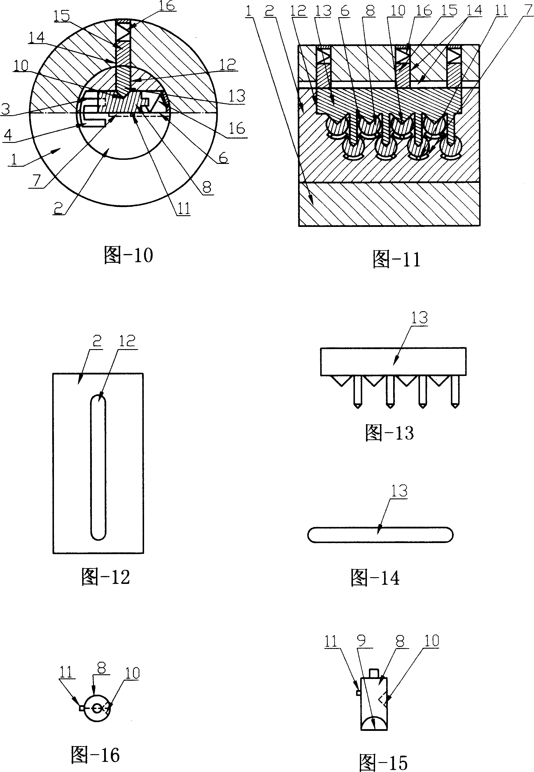
[0044] The second embodiment: a staggered arrangement of two rows of angled pinballs with restricted positions, and a spring is used as an anti-spin lock for pin pressure, and the structure is shown in Figs. 10 to 16. Compared with the first embodiment, the difference is that the original one row is changed to two rows of staggered marble holes (6), which have angular marbles (8), and the two rows of marble holes (6) are offset from the same side. The long side pin hole (12) communicates with the lock pin pin hole slot (14). In the through hole, there is an elongated comb-tooth side pin (13) whose head comb teeth are matched with the sidewall gaps (10) of the corresponding angle pin (8). A limit hole (7) is opened on the other side of each pin hole (6), and the same side of each angle pin (8) has a corresponding limit boss (11). Each pin hole (6) has a spring (16), each lock pin pin hole (14) has a lock pin (15) and a spring (16), and the key (4) has two rows of teeth arranged side b
Example Embodiment
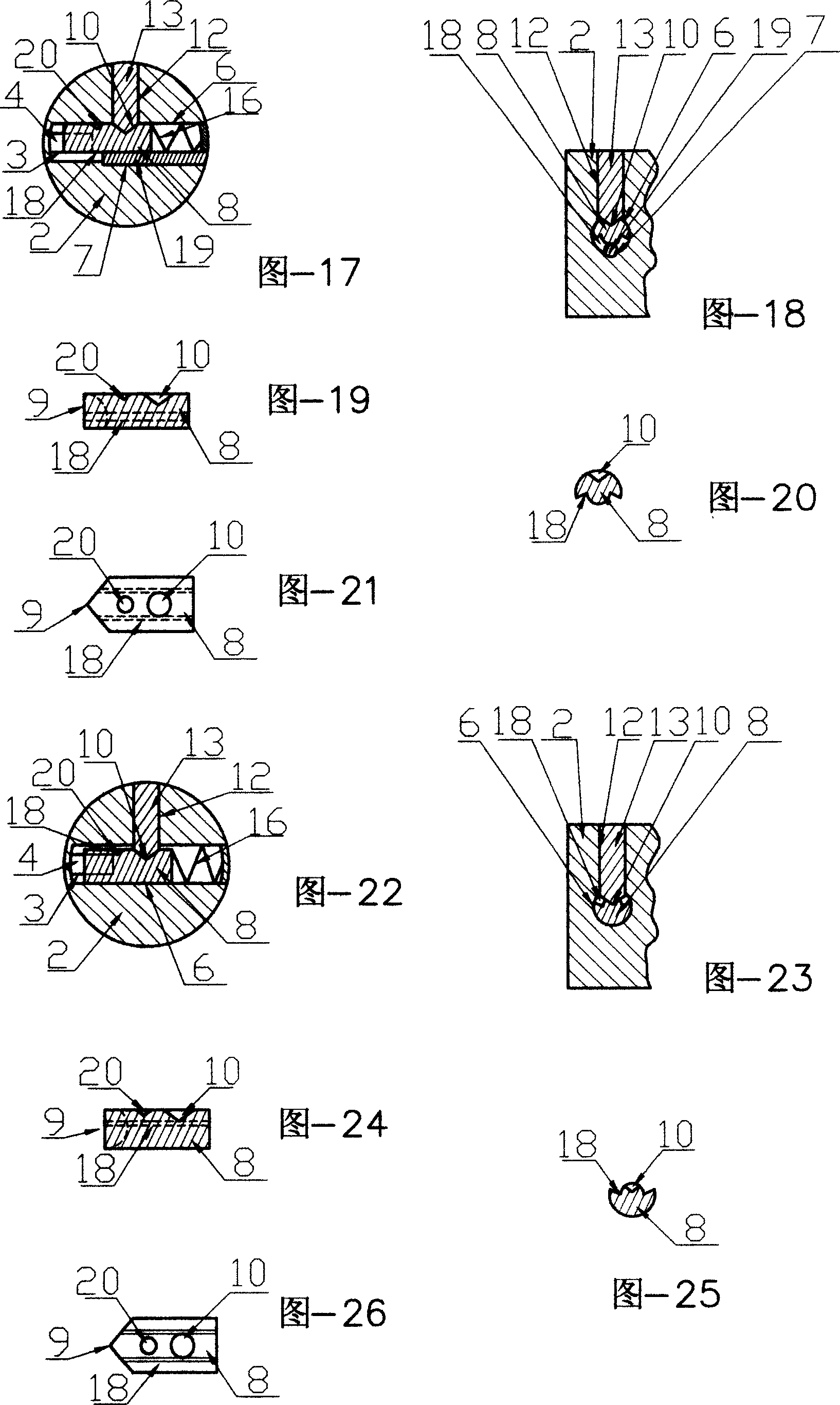
[0045] Embodiment 3: A two rows of angle marbles are arranged side by side, and a magnet is used as a lock for preventing the pressure of the side marbles. The structure is shown in Figs. 8 and 9. Compared with the first embodiment, the difference is that the original one row is changed to two rows of marble holes (6) arranged side by side. There are angular marbles (8) inside, and the two rows of marble holes (6) are respectively connected to one on each side. The elongated side pin hole (12) and the elongated lock pin hole (14) are communicated. There is a long side pin (13) in each of the two through holes, and the convex teeth on the head are matched with the corresponding angle pin (8) side wall gap (10), and the tail is with the long lock head. A pair of disassembled magnets (17) are arranged at the rear of the pin hole (14), springs (16) are arranged at the tails of the pins (8) of various angles, and two rows of teeth are arranged on the key (4).
[0046]The present invention
PUM
 Abstract
Description
Claims
Application Information
 - R&D Engineer
- R&D Manager
- IP Professional
- Industry Leading Data Capabilities
- Powerful AI technology
- Patent DNA Extraction
Browse by: Latest US Patents, China's latest patents, Technical Efficacy Thesaurus, Application Domain, Technology Topic.
© 2024 PatSnap. All rights reserved.Legal|Privacy policy|Modern Slavery Act Transparency Statement|Sitemap