Circuit with switch-off device for the operation of light sources

Inactive Publication Date: 2005-12-15
PATENT TREUHAND GESELLSCHAFT FUR ELECTRIC GLUEHLAMPEN MBH
View PDF16 Cites 5 Cited by
  • Summary
  • Abstract
  • Description
  • Claims
  • Application Information

AI Technical Summary

Benefits of technology

[0023] The first and second stages preferably contain bipolar transistors of a different types. For example, the first stage contains an NPN transistor and the second stage contains a PNP transistor. This makes it possible to join the two stages directly together. The collector of the first stage may be joined directly to the base of the second stage.
[0024] The second stage according to the invention can furthermore be used to suppress start pulses when the half-bridge inverter is commutating. To this end, the base of the transistor of the second stage is coupled with the drive signal of an electronic switch of the half-bridge inverter. Assuming that the electronic switches of the half-bridge inverter are turned on by a positive signal, the following combinations are particularly preferable: PNP transistor in the second stage coupled with the drive signal of the lower electronic switch; NPN transistor in the

Problems solved by technology

In fact, a start pulse while the upper electronic switch is turned on would actually destroy the half-bridge since a so-called cross current is set up.
One problem with the circuit according to the prior art is the dimensioning of the lowpass filter consisting of R4 and C4.
These

Method used


Image

  • Circuit with switch-off device for the operation of light sources
  • Circuit with switch-off device for the operation of light sources
  • Circuit with switch-off device for the operation of light sources

Examples


Embodiment Construction

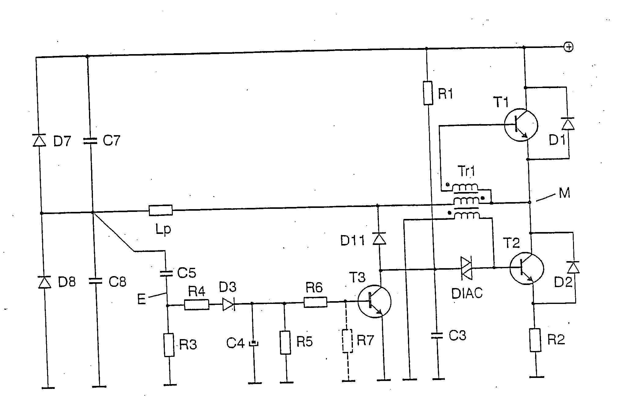
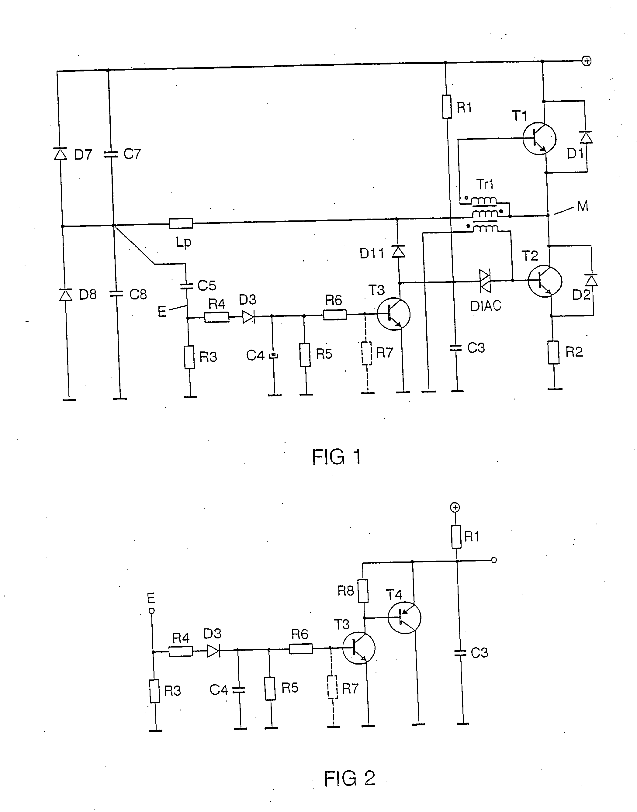
[0033]FIG. 2 represents an exemplary embodiment of a circuit according to the invention with a switch-off device for the operation of light sources. In comparison with FIG. 1, which represents the prior art, the switch-off device is expanded by the resistor R8 and the transistor T4. In contrast to the prior art, the collector of the transistor T3 is connected to the start capacitor C3 not directly but via R8. The collector of T4 is joined to the ground potential. T4 is therefore operated as a collector circuit. The emitter of T4 is joined to the start capacitor C3, and the base of T4 is joined to the collector of T3.

[0034] T3 forms the first stage as an emitter circuit, and T4 forms the second stage as a collector circuit. Owing to the second stage according to the invention, the collector current required by the first stage is reduced. The base current of the first stage is also thereby reduced, so that the base circuitry of T3 can have a higher impedance level. Values even less than


PUM


Abstract

A circuit with a switch-off device for the operation of light sources (Lp), has the following features: a self-commutated half-bridge inverter having a series circuit of an upper electronic switch and a lower electronic switch, which are joined at a half-bridge midpoint and are connected between a supply voltage and a ground potential, a start capacitor which is joined via a trigger element to a control electrode of the lower electronic switch, and a switch-off device having an input and an output, which are configured and connected so that they discharge the start capacitor if a switch-off signal is applied to the input. The switch-off device contains a time delay. In order to be able to keep the components in the time delay small, it is proposed that the switch-off device should comprise two successively connected transistor stages with bipolar transistors.

Description


Claims


Application Information

Patent Timeline
Owner PATENT TREUHAND GESELLSCHAFT FUR ELECTRIC GLUEHLAMPEN MBH
Why Eureka
Try Eureka