Image recording apparatus and image reading apparatus
- Summary
- Abstract
- Description
- Claims
- Application Information
AI Technical Summary
Benefits of technology
Problems solved by technology
Method used
Image

Examples
first embodiment
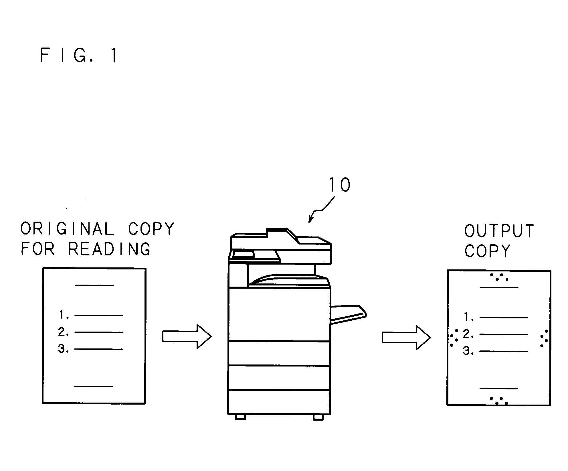
[0062]FIG. 1 is a schematic explanatory diagram for describing operations in the image recording apparatus according to the present invention. To be more specific, the image recording apparatus 10 according to the present invention is a copier or digital multi-function machine and equipped with a scanner function of optically reading an image of an original copy and a printer function of recording an image on a sheet such as a general sheet of paper and an overhead projector sheet based on input image data. When commanded to read an image of an original copy and record the read image on a sheet, namely, for copying of the original copy, the image recording apparatus 10 adds a pattern prepared in advance. The pattern which the image recording apparatus 10 adds is a letter, graphic image or symbol which contains information unique to the apparatus or an image combining these, and detection or analysis of the added pattern realizes identification of the origin of the copy. A pattern that
second embodiment
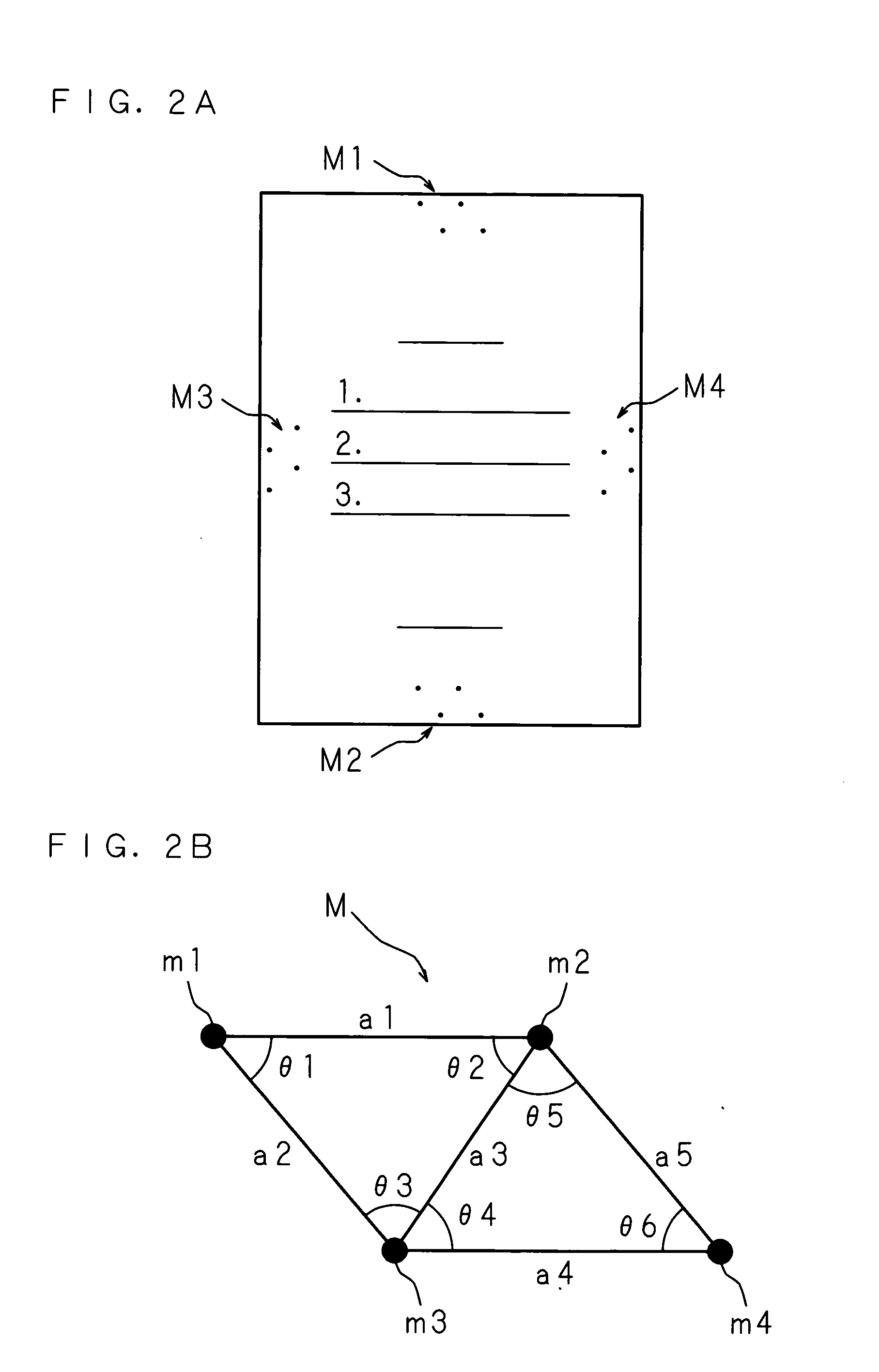
[0086] In the first embodiment directed to the structure in which whether specific patterns M are contained is detected after reading of an original copy has been completed and whether to permit copying is determined in accordance with the result of the detection, since the specific patterns M are located in peripheral sections of a sheet, it is possible to relatively quickly detect one of the specific patterns M regardless of the scanning direction of the original copy. Therefore, the reading of the original copy may be stopped upon detection of the specific pattern M while the original copy is being read. The structure of the image recording apparatus 10 according to this embodiment is identical to that according to the first embodiment, and hence, will not be described.
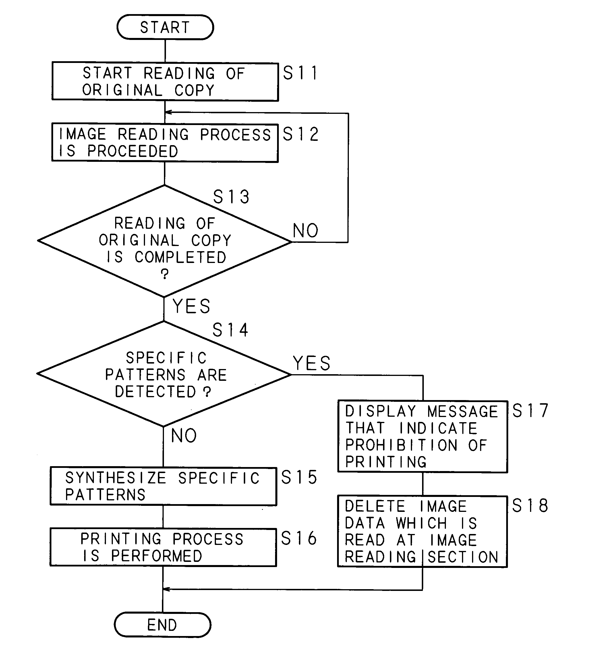
[0087]FIG. 11 is a flowchart for describing a processing sequence which the image recording apparatus follows in copying an original copy. When an instruction received on the operation panel 15 demands to start readi
third embodiment
[0091] Although the embodiments above require that for copying of an original copy to which no specific pattern M has been added, one type of specific patterns M are synthesized for image data acquired by the image reading section 20 and printing is performed based on the synthesized image data, a code (hereinafter referred to as a user code) which specifies a user may be accepted and a specific pattern M prepared for each user in advance may be added for copying of an original copy.
[0092]FIG. 13 is a block diagram showing the internal structure of a specific-pattern-synthesis section 17b according to this embodiment. The specific-pattern-synthesis section 17b according to this embodiment comprises an input buffer 171b which temporarily holds input image data, a user code managing section 173b which outputs select information with which a specific pattern is selected based on an input user code, a specific-pattern-managing section 174b which stores specific patterns and calculates the
PUM
 Abstract
Description
Claims
Application Information
 - R&D Engineer
- R&D Manager
- IP Professional
- Industry Leading Data Capabilities
- Powerful AI technology
- Patent DNA Extraction
Browse by: Latest US Patents, China's latest patents, Technical Efficacy Thesaurus, Application Domain, Technology Topic.
© 2024 PatSnap. All rights reserved.Legal|Privacy policy|Modern Slavery Act Transparency Statement|Sitemap