Multiplying digital to analog converter and multipath pipe line analog to digital converter using the same

Inactive Publication Date: 2006-05-25
ELECTRONICS & TELECOMM RES INST
View PDF15 Cites 2 Cited by
  • Summary
  • Abstract
  • Description
  • Claims
  • Application Information

AI Technical Summary

Benefits of technology

[0020] It is an advantage of the present invention to provide an analog to digital converter capable of efficiently removing an offset generated in each path with high speed and high resolution.
[0021] In particular, a purpose of the present invention is to provide a multipath pipelined analog to digital converter that is equipped with an improved multiplying digital to analog converter (MDAC).
[0022] In addition, another purpose of the present invention is to provide a MDAC that effectively removes offsets generated on multiple paths by diversifying an operating point of an amplifier in a MDAC circuit.
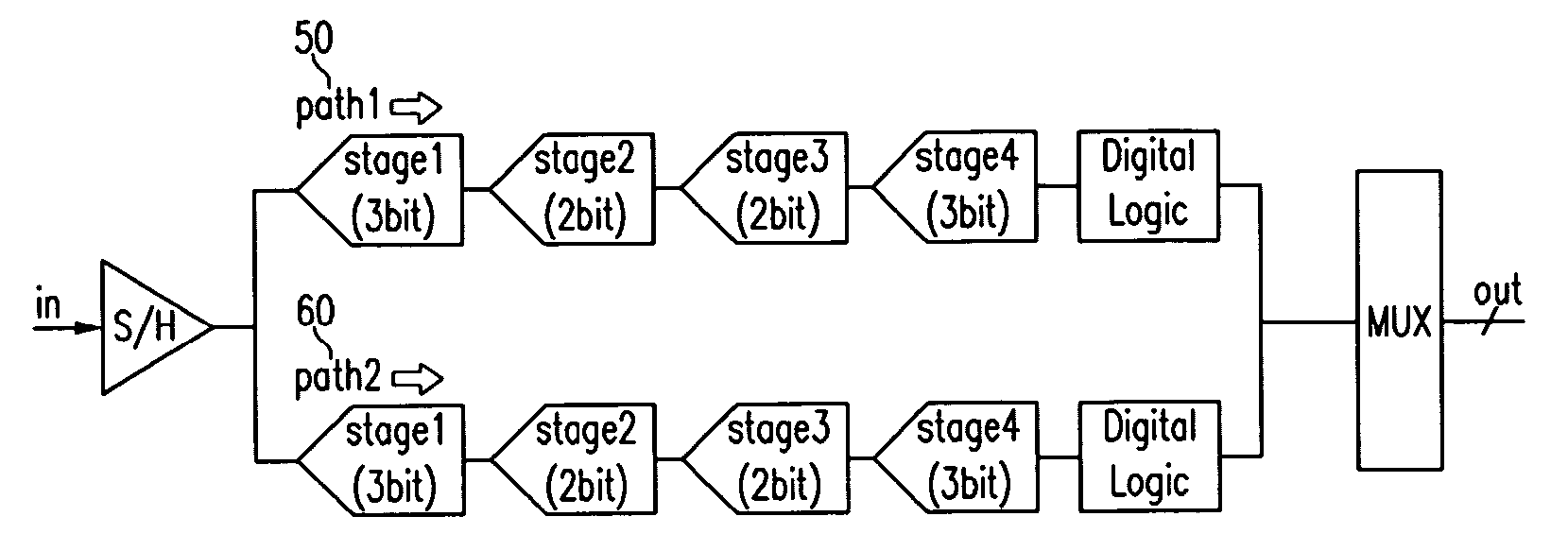
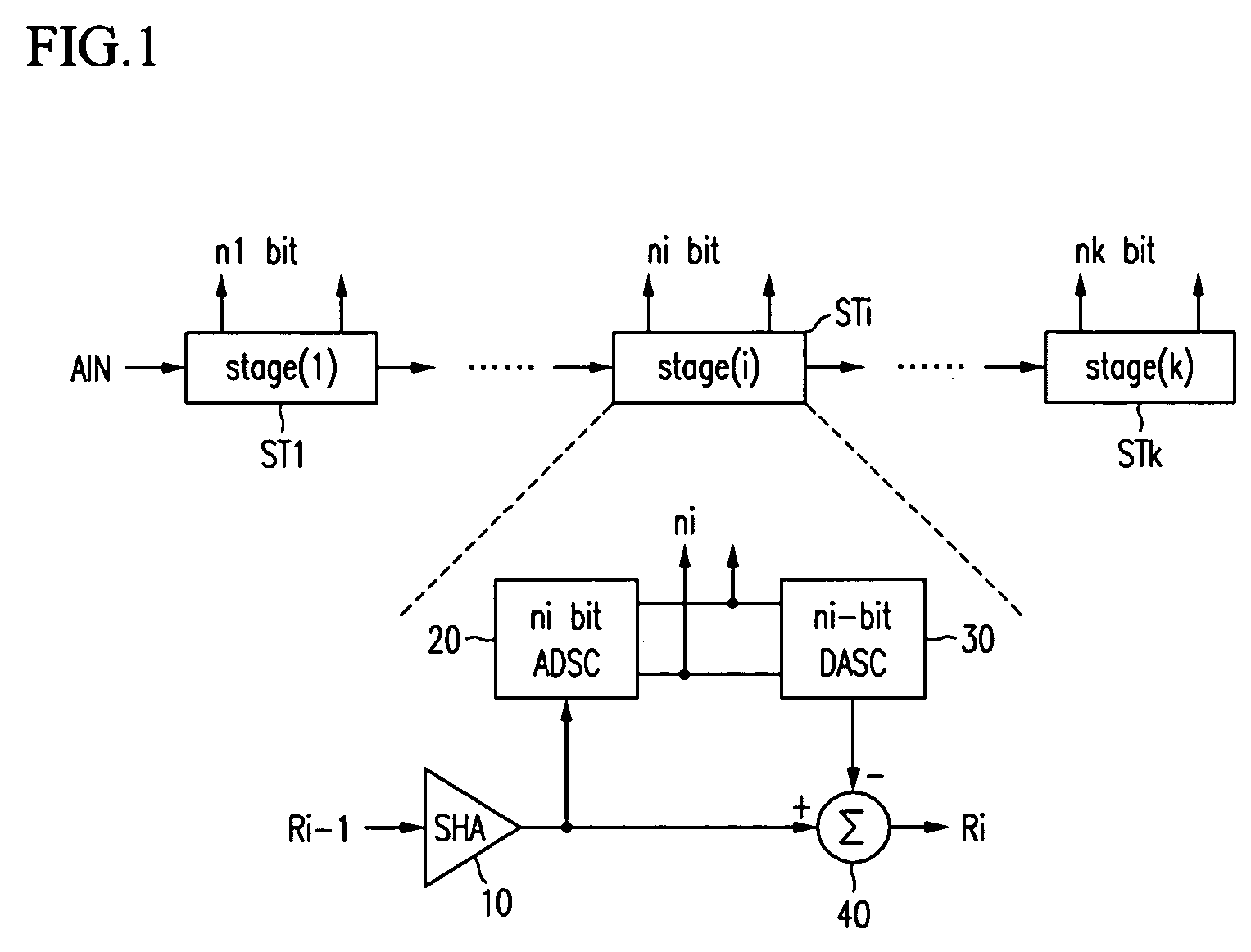
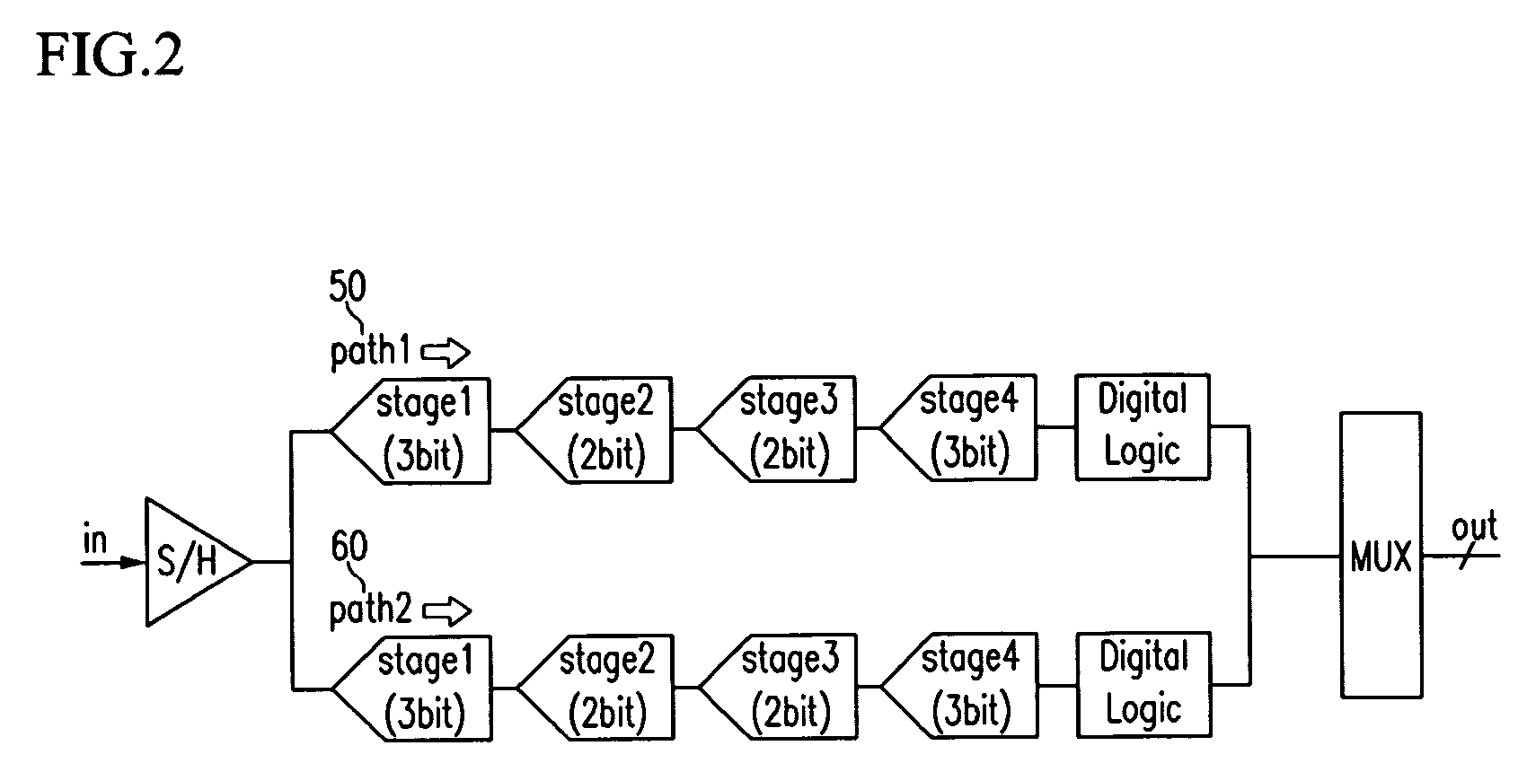
[0023] The multipath pipelined analog to digital converter includes a plurality of stages, and each stage includes a MDAC and an analog to digital converter. The number of bits in each stage of the analog to digital converter may be determined in consideration of a total number of bits, power consumption, and linearity.
[0024] In one aspect of the present invention, there is provided a multiplying digital to analog converter including a digital to analog converter and an amplifier. The digital to analog converter includes a plurality of capacitors coupled in parallel, applies first signals to the capacitors during a sampling period, and applies second signals to the capacitors during an amplifying period. The amplifier includes a first amplifier, a second amplifier, and a first switch. The first switch is turned off during the sampling period and turned on during the amplifying period. The first amplifier is coupled to the digital to analog converter, the second amplifier is coupled to the first amplifier, and the first switch is coupled between an input end and an output end of the second amplifier.
[0025] In another aspect of the present invention, there is provided a multiplying digital to analog converter including a digital to analog converter and an amplifier. The digital to analog converter includes a plurality of capacitors coupled in parallel, applies first signals to the capacitors during a sampling period, and applies second signals to the capacitors during an amplifying period. The amplifier includes a first amplifier, a second amplifier, a first capacitor, a second capacitor, and a first switch. The first switch is turned on during the sampling period, and turned off during the amplifying period. The first amplifier is coupled to the digital to analog converter, the second amplifier is coupled to the first amplifier, the first capacitor is coupled between an input end and an output end of the second amplifier, the second capacitor is coupled to both ends of the first capacitor, and the first switch is coupled between the first and second capacitors.

Problems solved by technology

However, when using multiple paths, an offset between the paths may be differentiated and thus each path may output different digital signals in response to the same analog signal input, thereby causing degradation of resolution.
Such a calibrating method requires additional operations to estimate offsets between the paths and adds circuit complexity to calibrate the offsets, thereby increasing cost.
However, the method has a problem of requiring a plurality of circuits for realizing the calibration algorithm thereby increasing cost.

Method used


Image

  • Multiplying digital to analog converter and multipath pipe line analog to digital converter using the same
  • Multiplying digital to analog converter and multipath pipe line analog to digital converter using the same
  • Multiplying digital to analog converter and multipath pipe line analog to digital converter using the same

Examples


Example

[0036] Hereinafter, the MDAC according to a first embodiment of the present invention will be described.

[0037] Referring to FIG. 3, the MDAC includes a digital to analog converter (DAC) 100 and an amplifier 200. The DAC 100 includes a first capacitor array (C1 to CN) 110, a second capacitor array (C1B to CNB) 120, first selection circuits S1 to SN, and second selection circuits S1B to SNB. The amplifier 200 includes a first amplifier A1, a second amplifier A2, compensation capacitors CC and CCB, feedback capacitors CF and CFB, and switches SW3, SW3B, SW4, SW4B, and SW5.

[0038] Typically, an n-bit MDAC requires 2n capacitors. ‘N’ in the capacitor arrays represents 2n, and ‘n’ represents a number of bits of a digital signal to be converted in each stage according to the first embodiment of the present invention.

[0039] In the DAC 100, first ends of capacitors C1 to CN in the first capacitor array 110 are respectively coupled to the first selection circuits S1 to SN. Meanwhile, first end

Example

[0066] With reference to FIG. 4, an MDAC according to a second embodiment of the present invention will be described.

[0067]FIG. 4 is a circuit diagram of the MDAC according to the second embodiment of the present invention.

[0068] As shown therein, the MDAC includes a DAC 100 which corresponds to the DAC in the first embodiment of the present invention, and an amplifier 300.

[0069] The amplifier 300 includes a first amplifier A1, a second amplifier A2, first compensation capacitors CC1 and CCB1, second compensation capacitors CC2 and CCB2, feedback capacitors CF and CFB, and switches SW3, SW3B, SW4, SW4B, and SW5.

[0070] A first end of the switch SW3 is coupled to input ends of the first capacitor array 110 and the first amplifier A1, and a second end thereof is coupled to an output end of the second amplifier A2. A first end of the switch SW4 is coupled to an output end of the first amplifier A1 and a first end of the first compensation capacitor CC1, and a second end thereof is coup

Example

[0084] Referring to FIG. 5, a MDAC according to a third embodiment of the present invention will be described.

[0085]FIG. 5 is a circuit diagram of the MDAC according to the third embodiment of the present invention.

[0086] As shown therein, the MDAC includes a DAC 100 and an amplifier 400. The DAC 100 is similar to the DAC 100 according to the first embodiment of the present invention, and thus a detailed description will be omitted.

[0087] The amplifier 400 includes a first capacitor array 110, a first amplifier A1, a second amplifier A2, compensation capacitors CC and CCB, feedback capacitor CF and CFB, switches SW3, SW3B, and SW4, and a bias control 410.

[0088] In the amplifier 400, a first end of the switch SW3 is coupled to inputs of the first capacitor array 110 and the first amplifier A1, and a second end thereof is coupled to an output end of the second amplifier A2. A first end of the compensation capacitor Cc is coupled to an input end of the second amplifier A2, and a secon


PUM


Abstract

A multiplying digital to analog converter comprising a digital to analog converter having a plurality of capacitors coupled in parallel, applying first signals to the capacitors during a sampling period, and applying second signals to the capacitors during an amplifying period, and an amplifier including a first amplifier electrically coupled to the digital to analog converter; a second amplifier electrically coupled to the first amplifier; and a first switch electrically coupled between an input end and an output end of the second amplifier, being turned off during a sampling period, and being turned off during an amplifying period.

Description


Claims


Application Information

Patent Timeline
Owner ELECTRONICS & TELECOMM RES INST
Why Eureka
Try Eureka