Shield wire, housing connected with same, connecting method thereof and shield wire unit

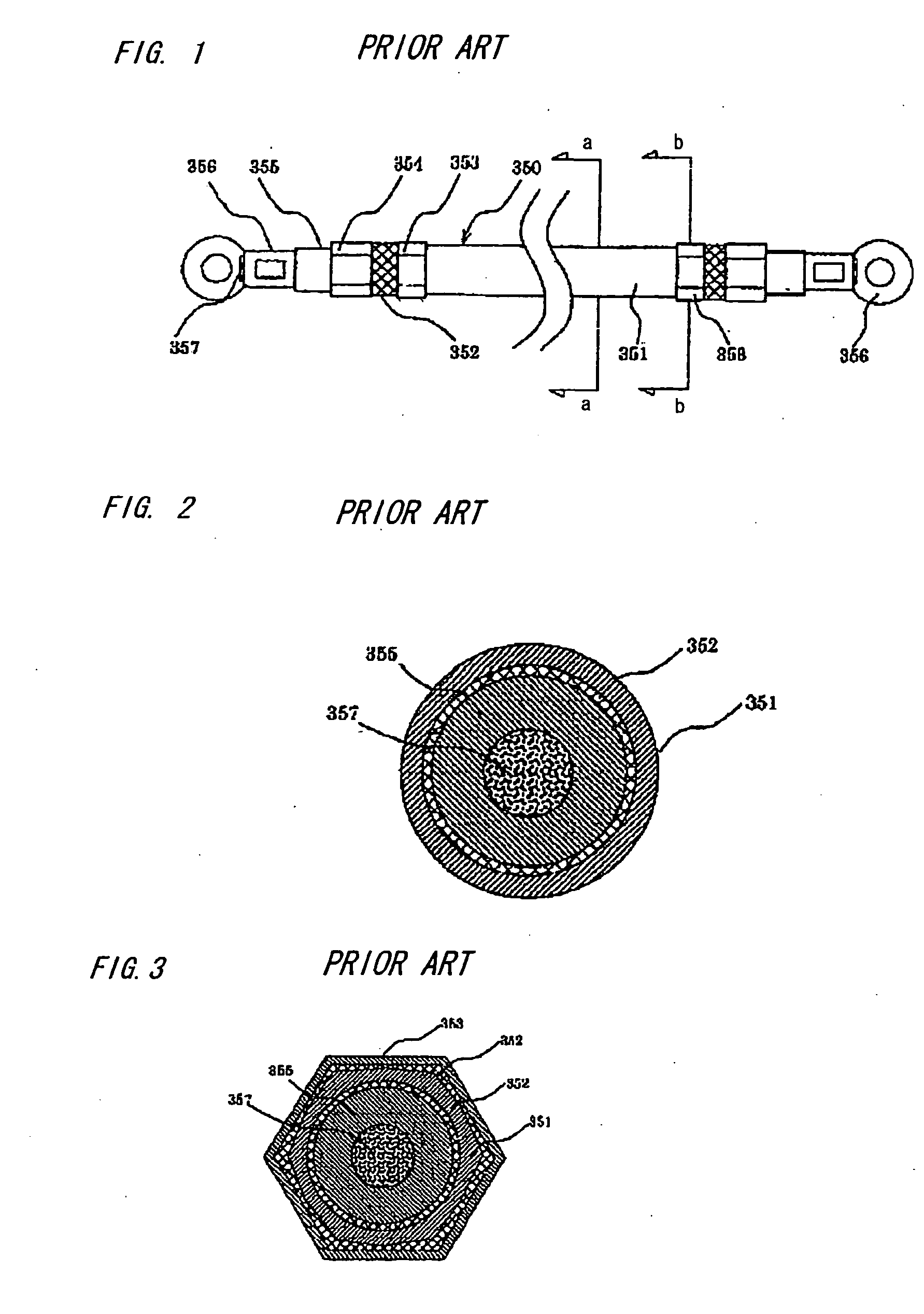
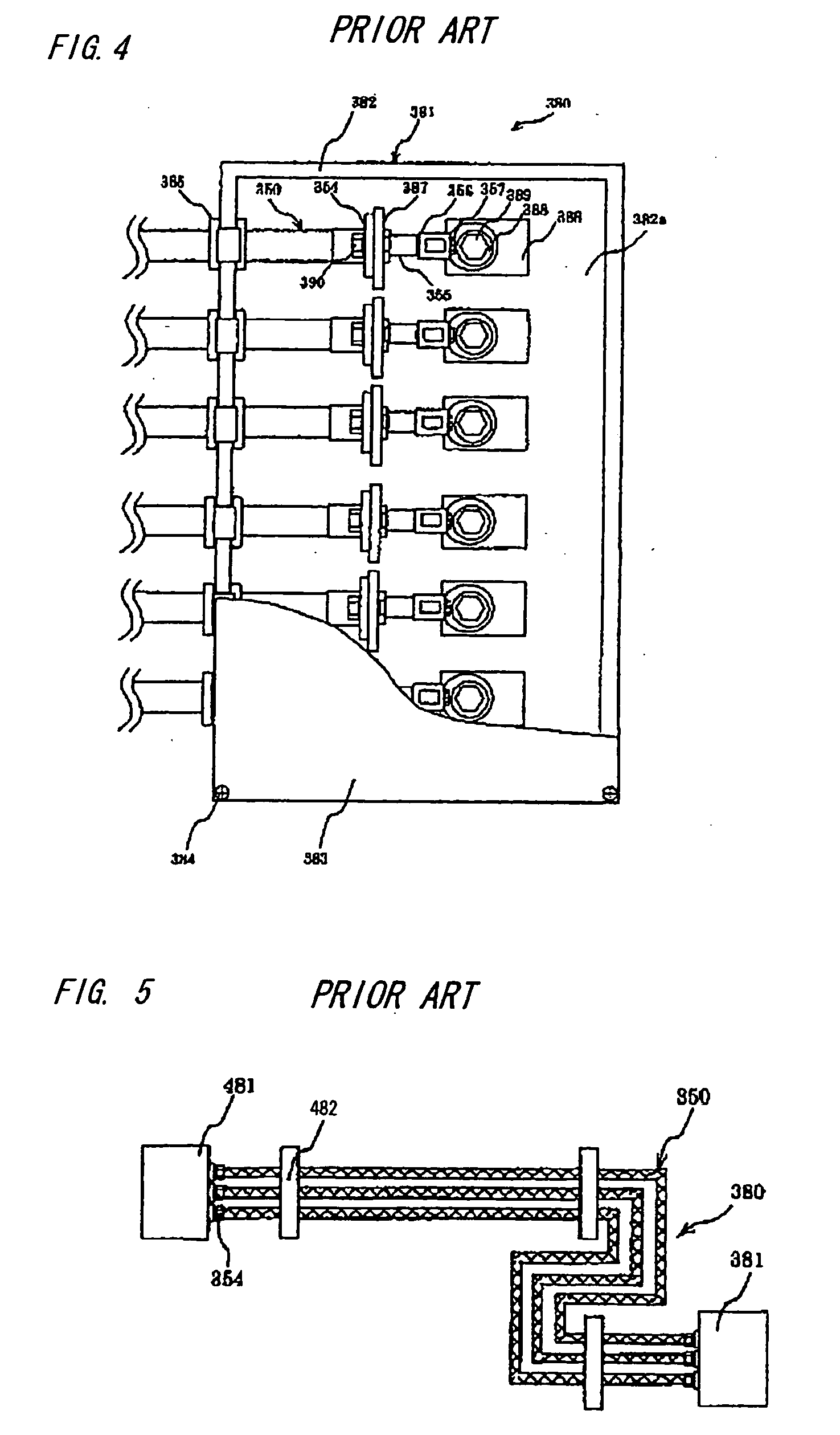
a shield wire and shield wire technology, applied in the field of shield wire, can solve the problems of vibration and heat, poor bending property of conventional shield wire 350, and poor handing property when subjected to vibration and heat, and achieve good bending property, shock resistance, and heat resistance

Inactive Publication Date: 2006-06-29
HITACHI METALS LTD
View PDF12 Cites 40 Cited by
  • Summary
  • Abstract
  • Description
  • Claims
  • Application Information

AI Technical Summary

Benefits of technology

The technical effect of this patented invention is to create a better way for wires used in electronic devices to withstand impacts from external sources such as collars or other objects. This can be done by adding layers made of materials like ceramic or plastic to improve its strength and durability against damage caused by external forces.

Problems solved by technology

This patent describes a technical problem addressed in the patent text relating to improving the flexibility and ease of handling of metal shield wires during attachment to connectors in vehicles. Existing methods involve using heat-resistive resin coatings or hardened covers to improve their strength against bending stress. These techniques require additional steps and laborious processes, leading to decreased efficiency and increased costs associated therewith.

Method used


Image

  • Shield wire, housing connected with same, connecting method thereof and shield wire unit
  • Shield wire, housing connected with same, connecting method thereof and shield wire unit
  • Shield wire, housing connected with same, connecting method thereof and shield wire unit

Examples


Embodiment Construction

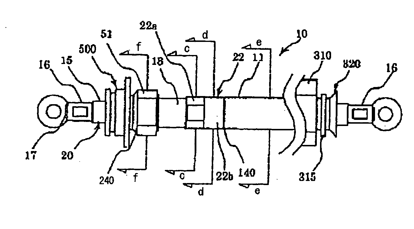
[0111]FIG. 6 is a plain view showing a shield wire in the preferred embodiment of the invention.

Composition of Shield Wire

[0112] As shown, the shield wire of this embodiment is composed such that a shield member is disposed around a wire main body 20 that a conductor 17 formed of single wire or stranded wire is covered with an insulation 15. The shield wire is provided with connection terminals 16, 16 at its both ends. One of the connection terminals 16, 16 (on the left side in FIG. 6) is connected to an inverter side as described later, and the other (on the right side in FIG. 6) is connected to a transmission side as described later.

Shield Member

[0113] The shield member is composed of a tubular body 50 as shown in FIG. 10 and a metal pipe 11 as shown in FIG. 16. The shield member is formed by abutting the tubular body 50 to the metal pipe 11 and then electrically connecting the tubular body 50 through a weld portion to the metal pipe 11. As shown in FIGS. 10 and 11, the tubular


PUM


Abstract

A shield wire has: a wire main body that has a conductor and an insulation covering the conductor, the conductor having a single wire or a stranded wire; and a shield member that is disposed on an outer circumference of the wire main body. The shield member has a tubular body having an inner sleeve, an braided shield and an outer sleeve, and a metal pipe is disposed on the outer circumference of the wire main body. The tubular body is electrically connected to the metal pipe at an end thereof. The shield wire further has a first connector member with a flange, wherein the first connector member is electrically connected to the tubular body at an other end of the tubular body where the tubular body is not connected to the metal pipe.

Description


Claims


Application Information

Patent Timeline
Owner HITACHI METALS LTD
Why Eureka
Try Eureka