Fault tolerant computer system and a synchronization method for the same
a computer system and fault-tolerant technology, applied in the field of fault-tolerant computer systems and synchronization methods for the same, can solve the problems of system operation stopping for a long time, affecting the efficiency of the system, and the contents of the main memory of the computer system in the operative state, so as to achieve the effect of reducing the performance of the computer system, preserving the simplicity of software control, and shortening the time period
- Summary
- Abstract
- Description
- Claims
- Application Information
AI Technical Summary
Benefits of technology
Problems solved by technology
Method used
Image

Examples
first embodiment
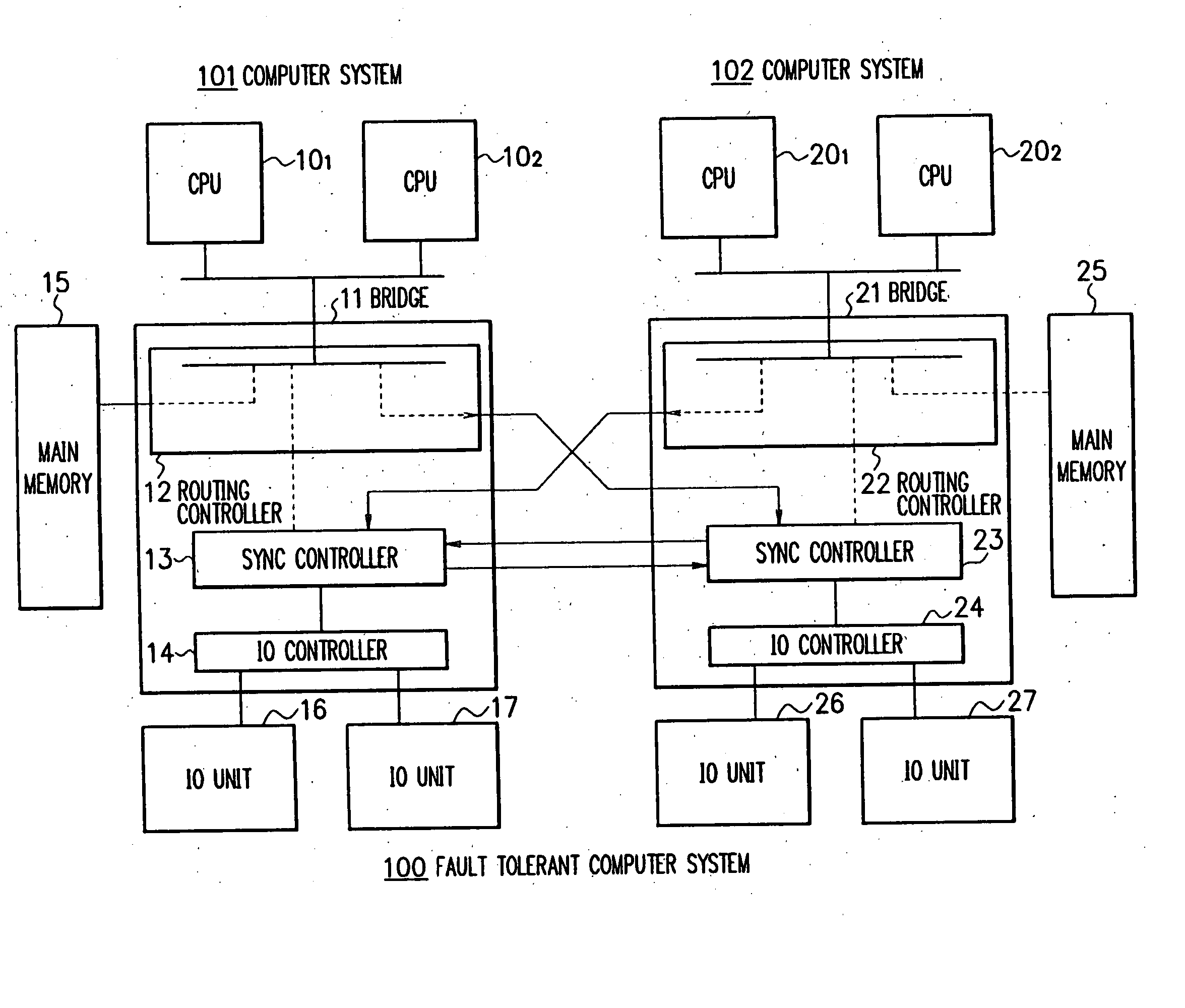
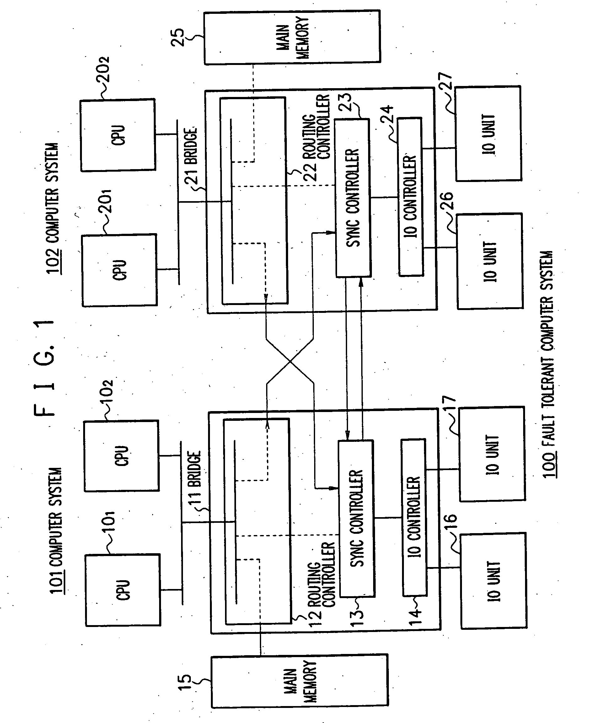
[0030]FIG. 1 is a block diagram showing a general configuration of a first embodiment in accordance with the present invention. In the configuration, a line connecting constituent components to each other is a bus or wiring, and an arrow indicates a direction of propagation of a signal. This also applies to FIGS. 2 and 6. As can be seen from FIG. 1 showing a fault tolerant computer system 100, the system 100 includes a computer system 101 and a computer system 102 which are substantially equal in structure to each other. Although the embodiment includes two computer systems, the fault tolerant computer system may include three or more computer systems. The computer systems 101 and 102 respectively include central processing units (CPUs) 101 and 102, and CPUs 201 and 202. Although each computer system includes two CPUs, the computer system may also includes one CPU or more than three CPUs. The CPUs 101 and 102 (201, 202) are connected via a bridge circuit 11 (21) to a routing controller
second embodiment
[0042]FIG. 6 shows in a block diagram a configuration of a second embodiment of the bridge circuit 11 in accordance with the present invention. The overall configuration of the second embodiment is substantially equal to that of the first embodiment. In FIG. 6, the constituent components equivalent to those of the first embodiment of FIG. 2 are assigned with the same reference numerals, and hence duplicated description of the bridge circuit 11 will be avoided. In the second embodiment, the read end counter is not used and only the read request counter 1223 is employed.
[0043] The operation flow of FIG. 7 shows a procedure to deliver data from the main memory 15 to the computer system 102 acting as the standby side in the second embodiment.
[0044] When the CPU of the computer system 101 issues at step S301 a synchronization start instruction to the sync controller 13, the read request counter 1223 is reset at step S302. The sync controller 13 then issues a read request to the memory con
PUM
 Abstract
Description
Claims
Application Information
 - R&D Engineer
- R&D Manager
- IP Professional
- Industry Leading Data Capabilities
- Powerful AI technology
- Patent DNA Extraction
Browse by: Latest US Patents, China's latest patents, Technical Efficacy Thesaurus, Application Domain, Technology Topic.
© 2024 PatSnap. All rights reserved.Legal|Privacy policy|Modern Slavery Act Transparency Statement|Sitemap