Multiple active coil speaker

Inactive Publication Date: 2006-08-24
FISHER MICHAEL
View PDF11 Cites 35 Cited by
  • Summary
  • Abstract
  • Description
  • Claims
  • Application Information

AI Technical Summary

Benefits of technology

[0020] An additional aspect of the invention is the advantageous use of non-active coils as components of accelerometers as passive coil generators generating signals upon movement past the permanent magnet and indicati

Problems solved by technology

Unfortunately deadening an enclosure's response cannot exactly match the resonant response at the resonant frequency.
Responses outside of the resonant range will also suffer distorting the frequency response of the cone.
Additionally, the conventional design fails to dissipate heat well as it also tends inherently to limit the length of travel for the voice tube.
The failure to dissipate heat limits the selection of materials for the magnets to generally ferrous materials.
Ferrous magnets tend to retain magnetism at higher temperatures while they are larger and by virtue of their size further limited in the ability to dissipate heat generated in the work of moving the voice tube.
Unfortunately, magnetic properties of NdFeB deteriorate rapidly above about 130 Centigrade, depending on the grade of material, and the permeance coefficient of the magnet in operation.
The higher the permeance coeff

Method used


Image

  • Multiple active coil speaker
  • Multiple active coil speaker
  • Multiple active coil speaker

Examples


Embodiment Construction

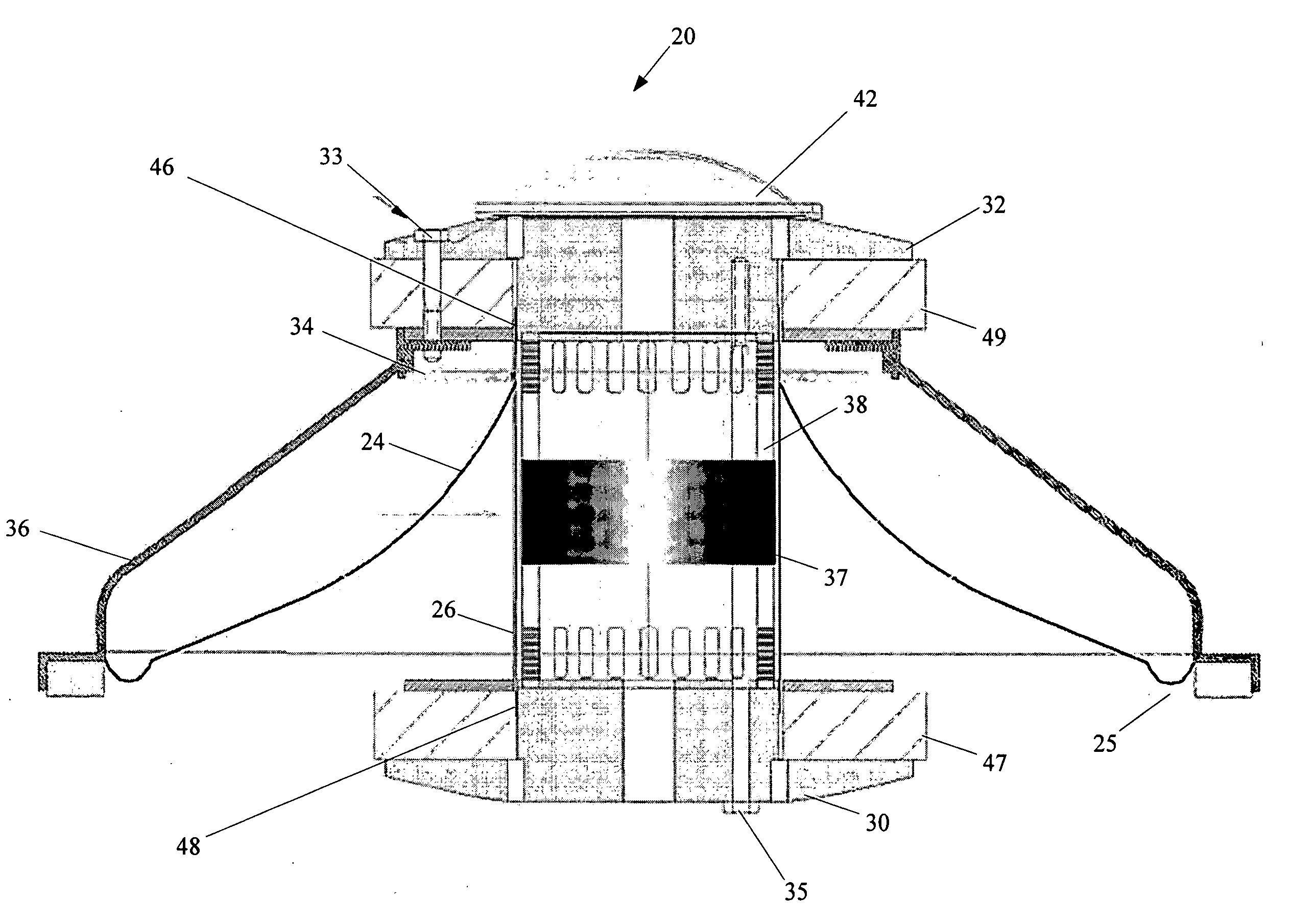
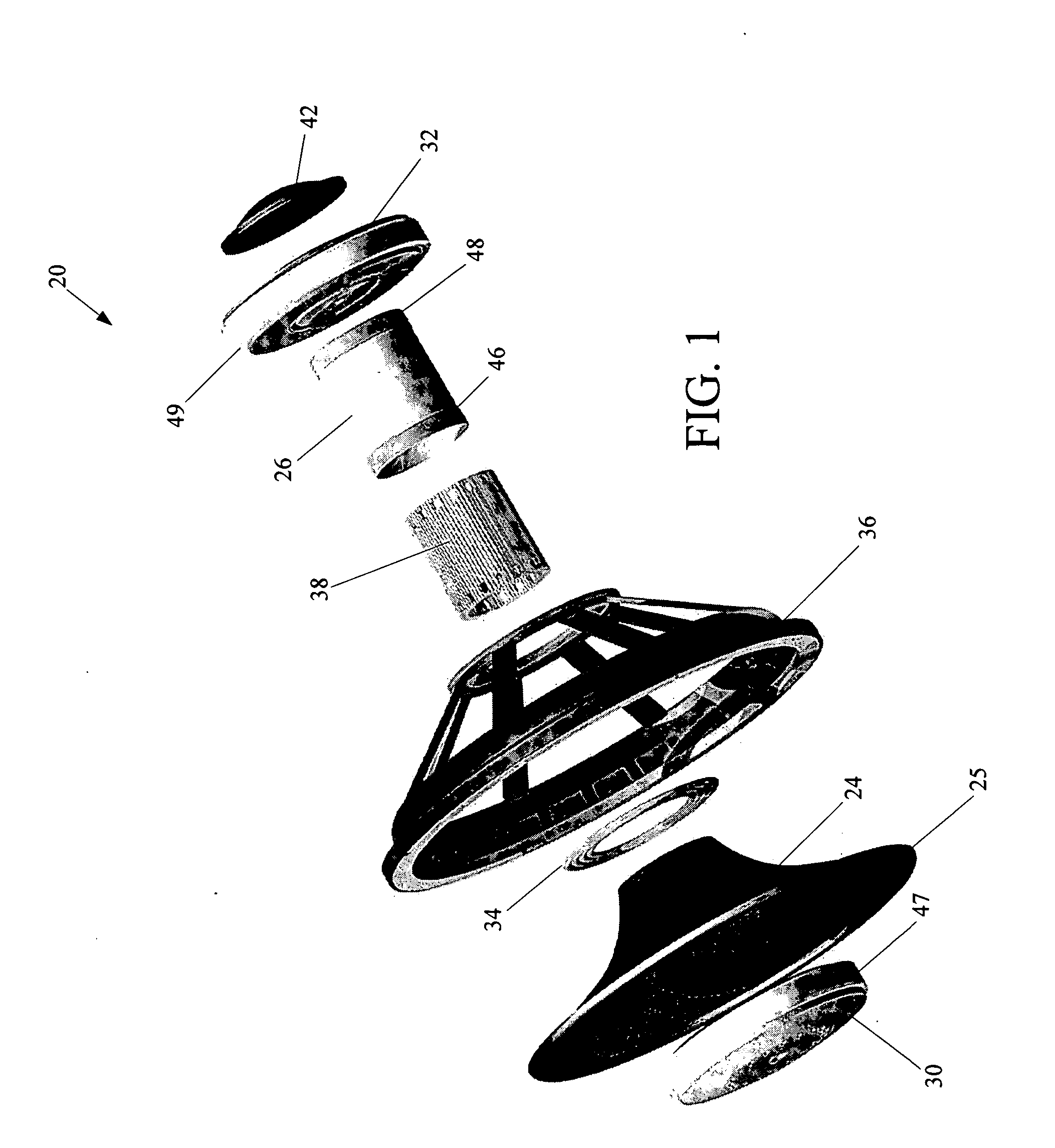
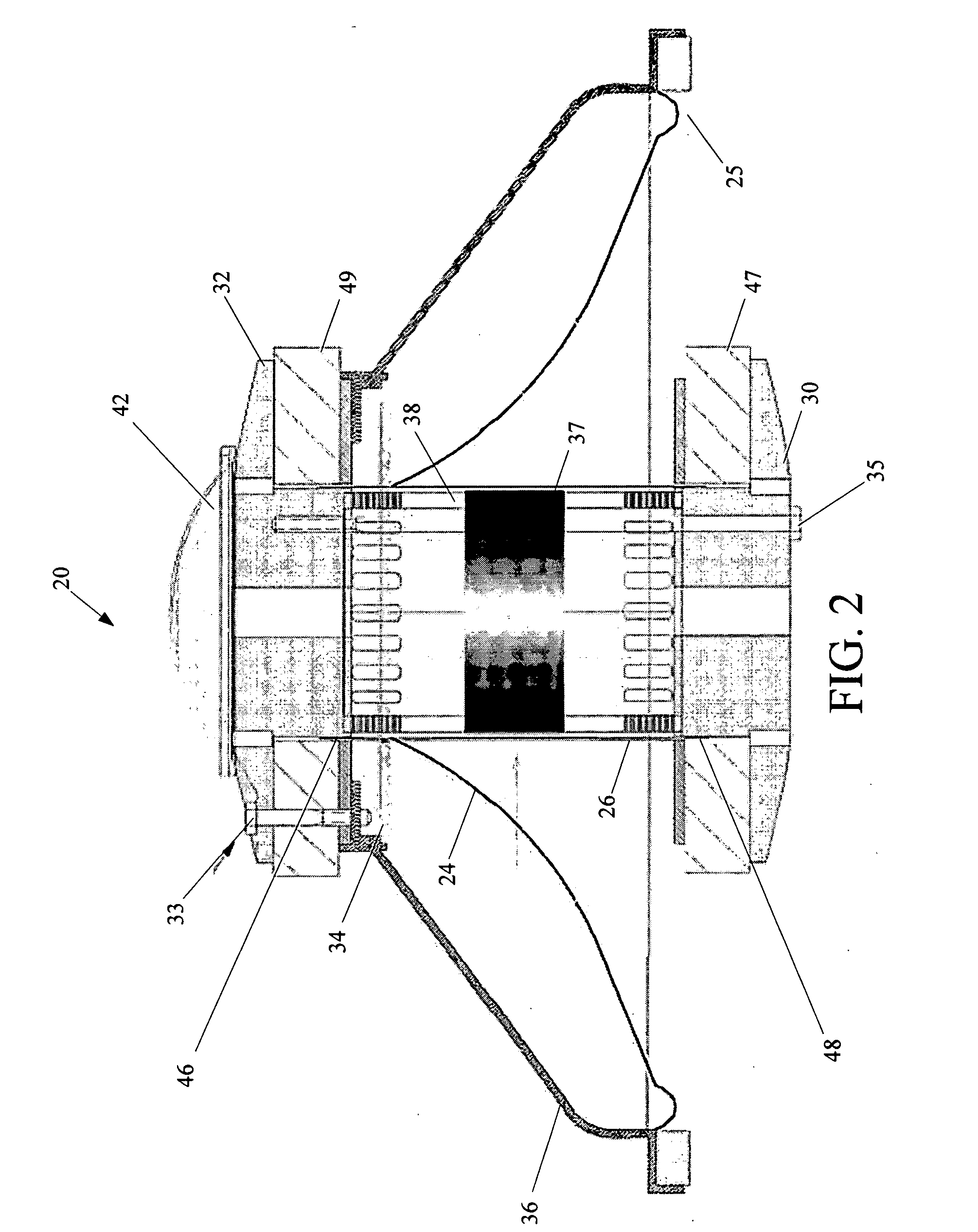
[0028] By way of overview, a voice tube assembly for a loudspeaker comprising a basket, a cone, and a spider includes a first magnet. The first magnet is configured for attachment onto the basket and has a principle axis. A second magnet, the second magnet configured the magnet being coaxial with the first magnet and spaced apart from it. A voice tube of non-ferrous material includes a cylindrical sleeve having a first extremity, a second extremity, and a cylinder axis. The cylinder axis is arranged to coincide with the principle axis. A first voice coil of conductive wire is wrapped around the first extremity in operational proximity to the first magnet. A second voice coil of conductive wire is wrapped around the second extremity in operational proximity to the second magnet.

[0029] A conventional loudspeaker is generally constructed of a metal frame or basket to which is attached, by means of an elastic surround, a cone, made of paper, plastic, or, rarely, metal. Near an apex of the


PUM


Abstract

A voice tube assembly for a loudspeaker comprising a basket, a cone, and a spider includes a first magnet. The first magnet is configured for attachment onto the basket and has a principle axis. A second magnet, the second magnet configured the magnet being coaxial with the first magnet and spaced apart from it. A voice tube of non ferrous material includes a cylindrical sleeve having a first extremity, a second extremity, and a cylinder axis. The cylinder axis is arranged to coincide with the principle axis. A first voice coil of conductive wire is wrapped around the first extremity in operational proximity to the first magnet. A second voice coil of conductive wire is wrapped around the second extremity in operational proximity to the second magnet.

Description


Claims


Application Information

Patent Timeline
Owner FISHER MICHAEL
Why Eureka
Try Eureka