Contactor material for welding wire feeder

a feeder and contactor technology, applied in the direction of circuit-breaking switches, circuit-breaking switches for excess current, manufacturing tools, etc., can solve the problems of contactor performance degeneration, contactor ultimately overheating, and welds performed during the welding cycle may require extensive rewelding or other corrective measures

Inactive Publication Date: 2006-08-31
LINCOLN GLOBAL INC
View PDF7 Cites 2 Cited by
  • Summary
  • Abstract
  • Description
  • Claims
  • Application Information

AI Technical Summary

Benefits of technology

This patent describes a new type of material that can be used on an electric arc welding machine's contactors instead of containing harmful substances like Cadmium.

Problems solved by technology

This patent describes a problem with traditional methods of replacing worn out contactors in an electric arc welder. These methods involve removing them after each use, which can lead to environmental concerns and potential health risks associated with these materials. Therefore, it is necessary to find a way to dispose of these harmful substances without causing any negative impacts on the environment.

Method used


Image

  • Contactor material for welding wire feeder
  • Contactor material for welding wire feeder
  • Contactor material for welding wire feeder

Examples


Embodiment Construction

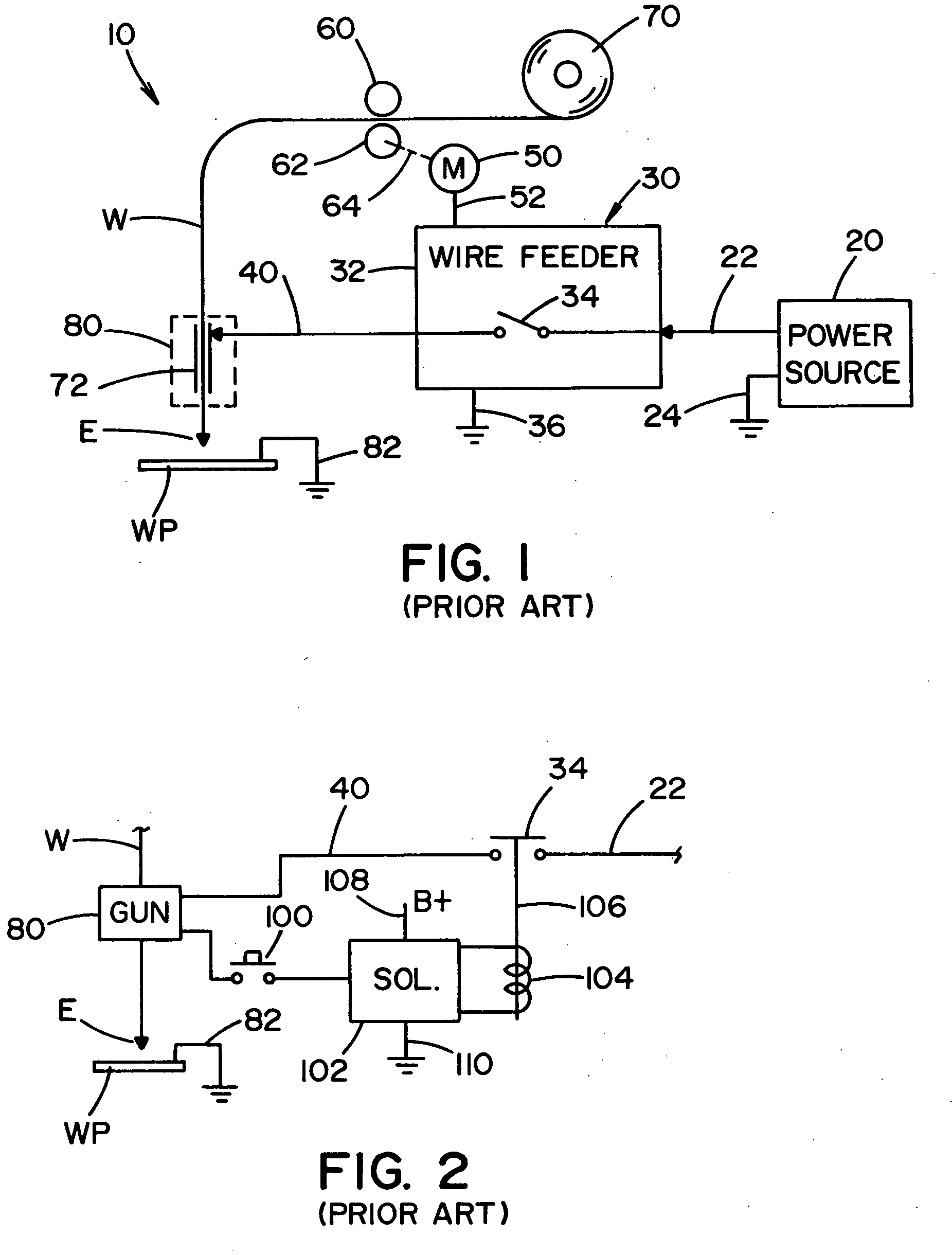
[0015] In the welding industry, a common product is an arc welder 10, as shown in FIG. 1 and schematically illustrated as including power source 20 with leads 22, 24. Wire feeder 30 enclosed in cabinet 32 has an internal electromechanical contactor 34 and a common ground 36. The wire feeder has an output welding lead 40 and a motor 50 operated at a speed determined by the signal on control line 52 from an internal microprocessor of the wire feeder. Motor 50 drives feed rolls 60, 62 through a shaft 64 to pull welding wire W from a supply, illustrated as reel or spool 70. The welding wire is moved through an electrical contact tip 72 located in welding gun 80 to direct electrode E toward workpiece WP for performing an electric arc welding process. The electrical circuit is completed by ground lead 82 attached to workpiece WP, in accordance with standard welding technology. In operation, contactor 34 is closed when a trigger switch within gun 80 is closed by an operator to drive wire W in


PUM


Abstract

An electromechanical contactor device is disclosed for use in a wire feeder for an electric arc welder having a power source and a gun with a contact tip through which welding wire is fed and a weld cycle start trigger switch having a closed condition to initiate and hold a weld cycle and an open condition. The contactor device comprises a power inlet lead connected to the power source, an output lead connected to the contactor tip, one or more current branches between the input lead and the output lead with a mechanical contactor having an open condition and closed condition for opening and closing the branches. A solenoid operates the contactor device based upon the condition of the trigger switch, with a first position to close the contactor when said trigger switch is shifted from the open condition to the closed condition and to hold the contactor closed when the trigger switch is in the closed condition. The contactor device utilizes one or more sets of electrical contacts formed from non-hazardous silver alloys.

Description


Claims


Application Information

Patent Timeline
Owner LINCOLN GLOBAL INC
Why Eureka
Try Eureka