Self-alignment spacer for a ball screw device

Inactive Publication Date: 2006-09-07
HIWIN TECH
View PDF4 Cites 8 Cited by
  • Summary
  • Abstract
  • Description
  • Claims
  • Application Information

AI Technical Summary

Benefits of technology

[0010] The primary objective of the present invention is to provide a self-alignment spacer for a ball screw device being able to rotate in response to an acceleration force during operation. The spacer has two different specific gravities which are used to make the center of gravity of the spacer be eccentrically positioned, so as to produce a tumbler effect to make the spacer between the respective balls rotate in response to gravity and centrifugal force, thus preventing the spacer from being tip over. The above-mentioned gravity and centrifugal force are called acceleration force, gravity is a gravity acceleration force caused by an attraction force between the spac

Problems solved by technology

The spacers 11 are always required to be minimized and unitary-structured, however, such spacers are impractical due to the following reasons:
For example, a ball screw device disclosed by U.S. Pat. No. 6,565,947, as shown in FIG. 2, wherein the spacer 11 is provided with two grooves 12, 13, however, the clearances between the balls 10 also can be accumulated to form a space large enough to cause the spacer 11 to be h

Method used


Image

  • Self-alignment spacer for a ball screw device
  • Self-alignment spacer for a ball screw device
  • Self-alignment spacer for a ball screw device

Examples


first embodiment

[0028] For better understanding the operation and the function of the first embodiment, references should be made again to FIG. 6-9.

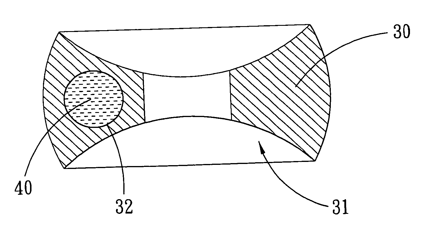
[0029] Since the stuffing 40 is stuffed into the receiving space 32 of the spacer 30 which is located off-center in the spacer 30, the specific gravity of the stuffing 40 is greater than that of the spacer 30, so that the center-of-gravity of the spacer 30 is eccentrically positioned. When the clearances between the respective balls 20 are accumulated at the upper and the lower sides of the screw shaft 50, the eccentric center of gravity of the spacer 11 will produce a force T (like a tumbler) to prevent the spacer 11 from tipping over. When the clearances between the respective balls 20 are accumulated at the both lateral sides of the screw bolt 50, the eccentric center of gravity of the spacer 11 will cause the spacer 11 to tumble down on the surface of the screw shaft 50, however, when the spacer 11 moves to the upper or the lower sides of the screw sha

second embodiment

[0030] Referring to FIGS. 10-12, which show the present invention, at either side of the respective spacers 60 is formed an arc-shaped recess 61 in response to the surface of the ball 20, in the spacer 60 is formed an annular passage 62 which surrounds the center of the spacer 60.

[0031] A stuffing 70 is a liquid having a specific gravity greater than that of the spacer 60 and occupies a part of the annular passage 62, so that the center-of-gravity of the spacer 60 is eccentrically positioned.

[0032] Since the stuffing 70 is a liquid and only occupies a part of the annular passage 62 of the spacer 60, it will keep flowing, during the movement of the spacer 60, to adjust the center of gravity of the spacer 60 continuously. When the clearances between the respective balls 20 are accumulated at the upper and the lower sides of the screw shaft, the liquid-like stuffing 70 will adjust the center of gravity of the spacer 60, thus producing a force T to prevent the spacer 60 from tip over. Sin


PUM


Abstract

A self-alignment spacer for a ball screw device is disposed between respective balls of a ball screw device and comprises: at least a stuffing having a specific gravity different from that of the spacer, a center of gravity of the spacer being eccentrically positioned, so that, in operation, the spacer between the respective balls will be able to rotate in response to an acceleration force thereof.

Description


Claims


Application Information

Patent Timeline
Owner HIWIN TECH
Why Eureka
Try Eureka