Control device for automatic machine

Inactive Publication Date: 2006-09-14
YASKAWA DENKI KK
View PDF13 Cites 16 Cited by
  • Summary
  • Abstract
  • Description
  • Claims
  • Application Information

AI Technical Summary

Benefits of technology

[0015] As previously described, in accordance with the control apparatus of the present invention, when the driving power supply is turned ON, after the contacts of the relay apparatus have been closed, since a feed control operation for adjusting a feed starting angle of an AC voltage is carried out by the current control rectifying element, the contacts of the relay apparatus are closed under no voltage, and a rush current is suppressed. As a result, a damage given to the contacts of the relay apparatus can be avoided.

Problems solved by technology

However, if the resistance value is decreased, then the rush current cannot be sufficiently suppressed, so that the temperature of the resistor conductor instantaneously becomes high due to the own heat generation every time the driving power supply is turned ON, and after the contacts of the relay are closed, the relay is brought into the non-feeding condition.
The resistor conductor is repeatedly expanded and shrunk due to the above-explained heat generation, and thus, there are some possibilities that a wire disconnection failure may occur due to metal fatigue.
As a consequence, such a resistor having a large capacity must be selected, namely, a resistor having a large outer dimension must be selected, resulting in a problem, since the control ap

Method used


Image

  • Control device for automatic machine
  • Control device for automatic machine
  • Control device for automatic machine

Examples


first embodiment

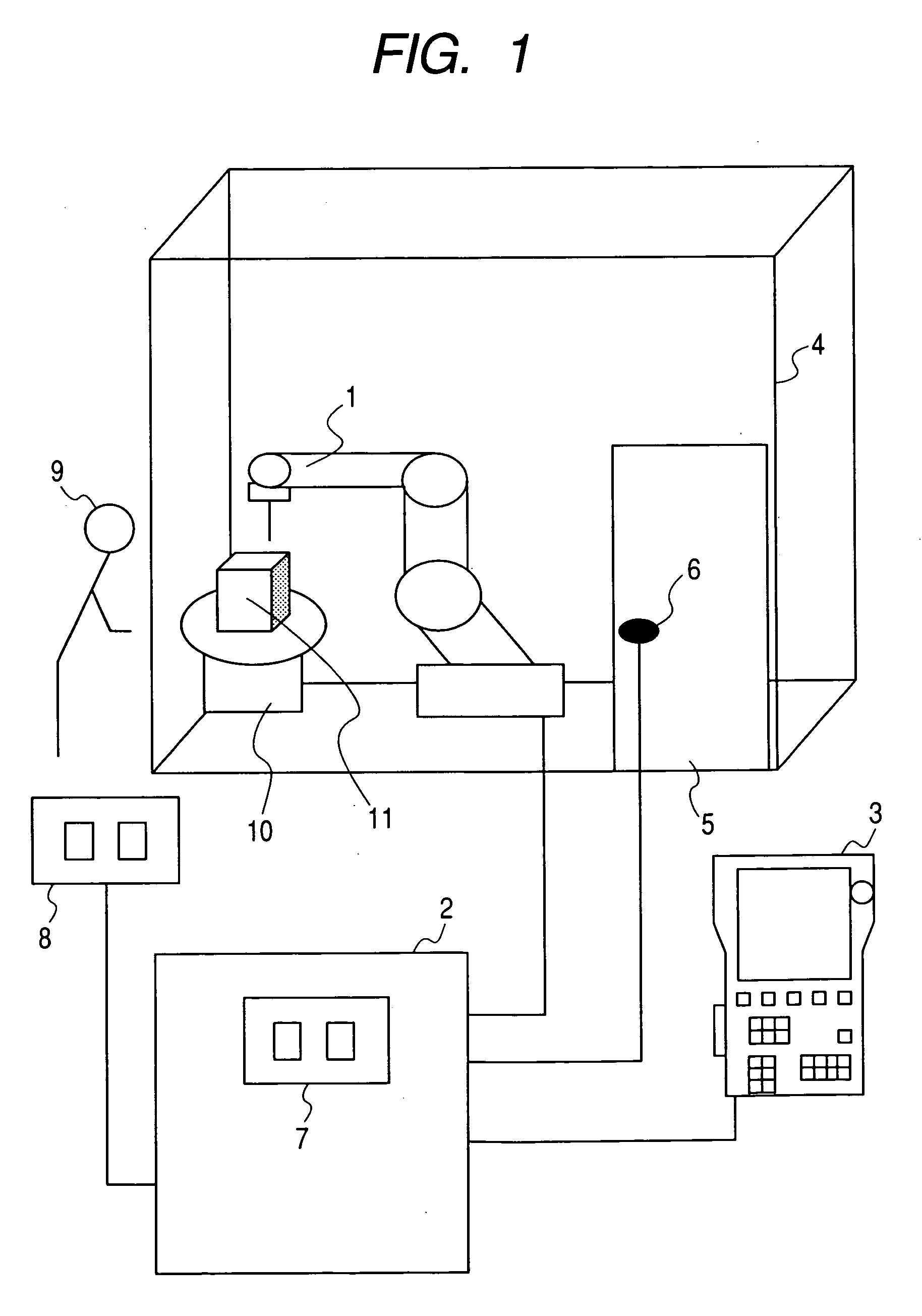
[0024]FIG. 1 is a diagram for indicating an arrangement of both a robot control apparatus and a robot system, which represent the present invention.

[0025] In the drawing, reference numeral 1 indicates a robot, and the robot 1 has been connected to a robot control apparatus 2. A work tool used to perform a work has been mounted on a tip of a wrist portion of the robot 1. A pendant 3 has been connected to the robot control apparatus 2. The pendant 3 performs editing operations such as a registration of a work program, or a change in a registered work program by causing the robot 1 to be actuated in a teaching operation so as to execute a position registration, or by registering a work. Also, the robot system has been equipped with a protection fence 4, a protection fence door 5 of a doorway for the protection fence 4, and a door open / close detecting apparatus 6, while this door open / close detecting apparatus 6 has been connected to the robot control apparatus 2. The protection fence


PUM


Abstract

A control apparatus of an automatic machine is provided, while the control apparatus supplies electric power of a power supply in high reliability with respect to a driving apparatus of the automatic machine, and further, has no problem as to ensuring of safety.
In a control apparatus of an automatic machine having a breaker (22) connected to a power supply (21), and a driving apparatus (32) for supplying electric power of the power supply (21) to a driving unit (35) of the automatic machine via a relay apparatus (31) connected to the breaker (21), which controls the driving apparatus (32), the control apparatus is comprised of: a current control rectifying element (33) connected to the relay apparatus (31); and a current controlling device (29) for feed-controlling the current control rectifying element (33) after a contact of the relay apparatus (31) has been closed when supplying of the electric power to the driving unit (35) is turned ON.

Description


Claims


Application Information

Patent Timeline
Owner YASKAWA DENKI KK
Why Eureka
Try Eureka