Method and apparatus for resource-based thread allocation in a multiprocessor computer system

a multi-processor computer system and resource-based thread technology, applied in multi-programming arrangements, program control, instruments, etc., can solve problems such as thread conflict potential

Inactive Publication Date: 2007-05-03
IBM CORP
View PDF13 Cites 15 Cited by
  • Summary
  • Abstract
  • Description
  • Claims
  • Application Information

AI Technical Summary

Benefits of technology

The technical effect described by this patented method allows users to determine whether two or more threads can access different resources simultaneously without interfering each other's data streams. This helps improve efficiency when accessing shared memory systems like servers.

Problems solved by technology

The technical problem addressed in these documents relates to conflicting between different types of processing units running simultaneously or overlapping them due to their shared resource called PEB.

Method used


Image

  • Method and apparatus for resource-based thread allocation in a multiprocessor computer system
  • Method and apparatus for resource-based thread allocation in a multiprocessor computer system
  • Method and apparatus for resource-based thread allocation in a multiprocessor computer system

Examples


Embodiment Construction

[0024] In the following detailed description of the preferred embodiments, reference is made to the accompanying drawings illustrating embodiments in which the invention may be practiced. It should be understood that other embodiments may be utilized and changes may be made without departing from the scope of the present invention. The drawings and detailed description are not intended to limit the invention to the particular form disclosed. On the contrary, the intention is to cover all modifications, equivalents and alternatives falling within the spirit and scope of the present invention as defined by the appended claims. Headings herein are not intended to limit the subject matter in any way.

[0025] System

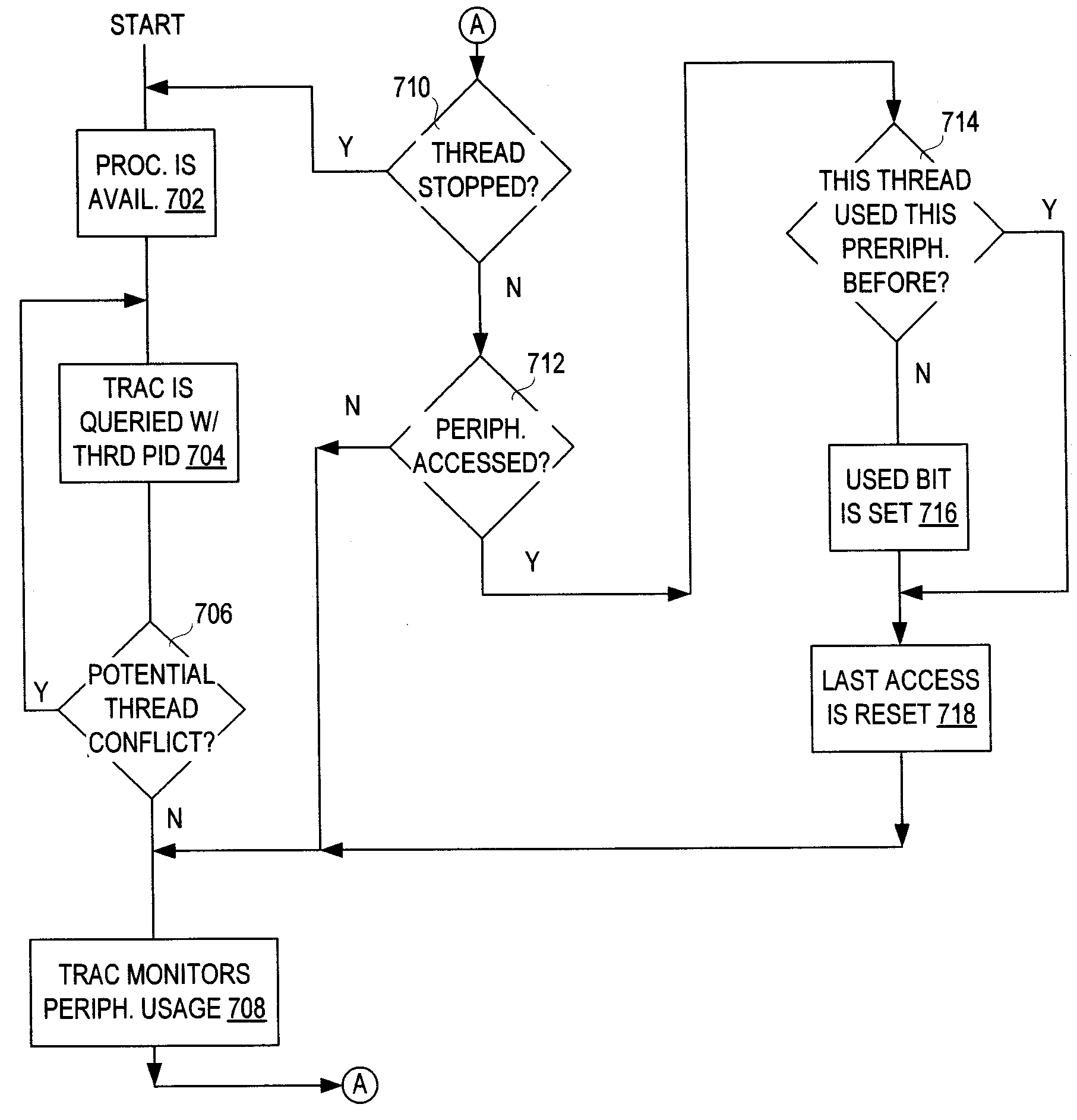
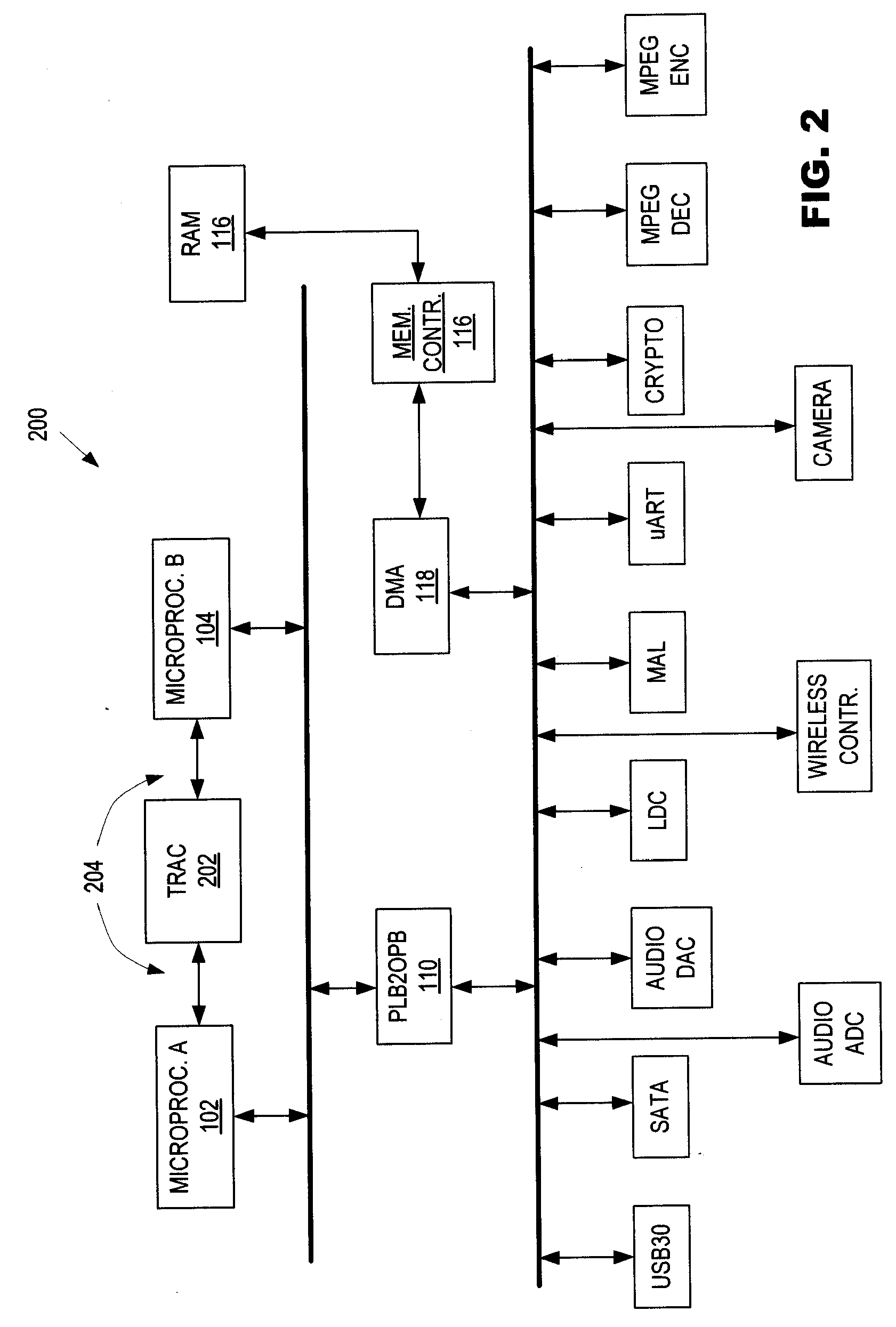
[0026] As previously stated, in a multiple processor environment, multiple threads run literally at the same time and thus may compete to use the same peripheral devices. According to an embodiment of the present invention, thread resource allocation logic (also referred to herei


PUM


Abstract

Thread entries are stored in a memory of the system to indicate executed instruction threads. Uses of processing resources by the respective instruction threads are detected and history entries for the threads are stored in a memory of the system. Such history entries indicate whether respective processing resources have been used by respective ones of the instruction threads. The history entries of first and second ones of the instruction threads are compared. The second instruction thread is selected for executing if the comparing indicates history of processing resources used by the first thread has a certain difference relative to history of processing resources used by the second thread.

Description


Claims


Application Information

Patent Timeline
Owner IBM CORP
Why Eureka
Try Eureka