Resistored anode construction

a technology of resistors and anodes, which is applied in the direction of fluid heaters, lighting and heating apparatus, and immersion heating arrangements, etc., can solve the problems of reducing the useful life of anodes, affecting the service life of anodes, so as to inhibit vessel corrosion

Active Publication Date: 2007-06-07
RHEEM MFG CO
View PDF13 Cites 9 Cited by
  • Summary
  • Abstract
  • Description
  • Claims
  • Application Information

AI Technical Summary

Benefits of technology

The present invention provides a special design for a metal liquid container used in a water heating system that prevents it from getting damaged by chemicals or other substances stored inside. This is achieved through a special type of anodes made of materials like tantalum nitride (TaN) which are resistant to corrosion.

Problems solved by technology

The technical problem addressed in this patent is how to improve the durability and resistance of anode assemblies used in protective anode assemblies for use in tanks containing metallic waters. Current methods involve adding sacrificial anodes made of tin or copper to reduce wear and tear caused by the anode's own weight. However, they may still result in damage to the anode itself due to the vapor pressure generated during the electrode production process. Therefore, the invention proposes a new design for an improved anode assembly that prevents excessive straining and failure of the anode without compromising the strength of the anode.

Method used


Image

  • Resistored anode construction
  • Resistored anode construction
  • Resistored anode construction

Examples


Embodiment Construction

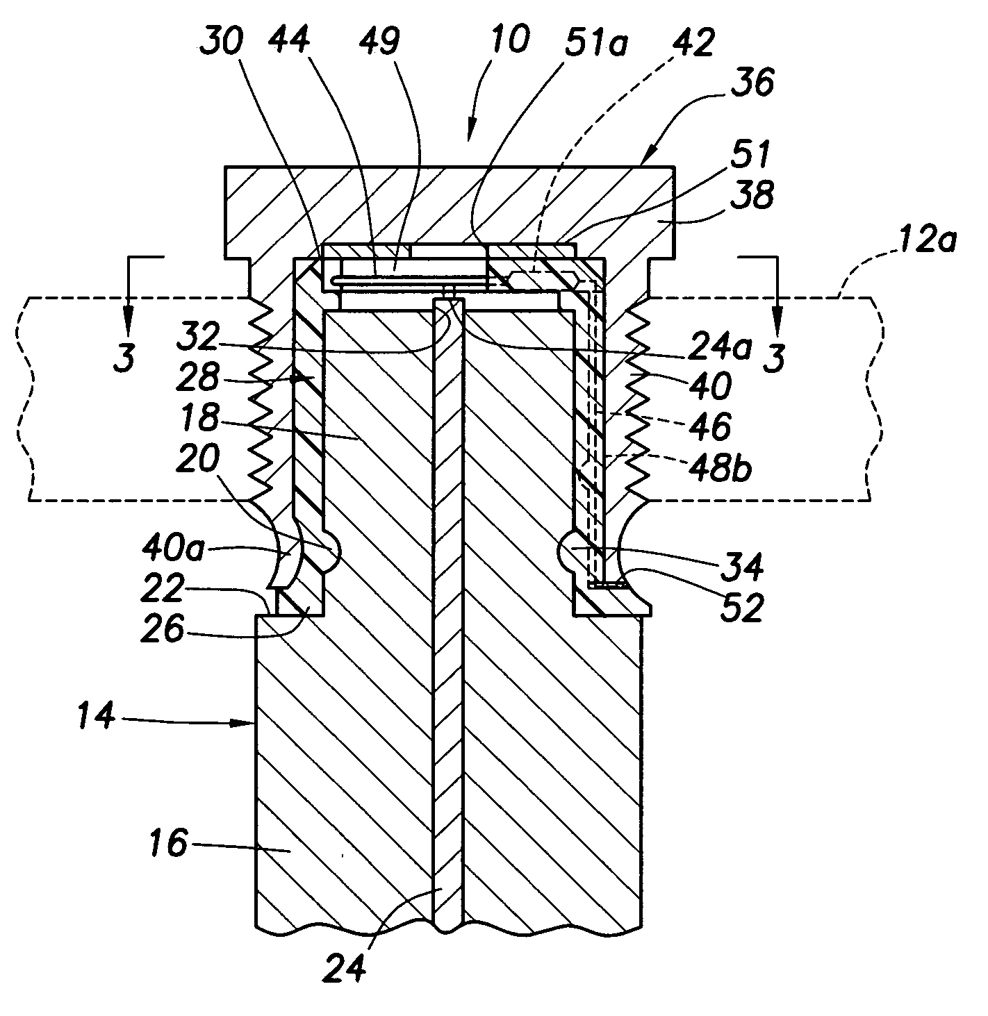
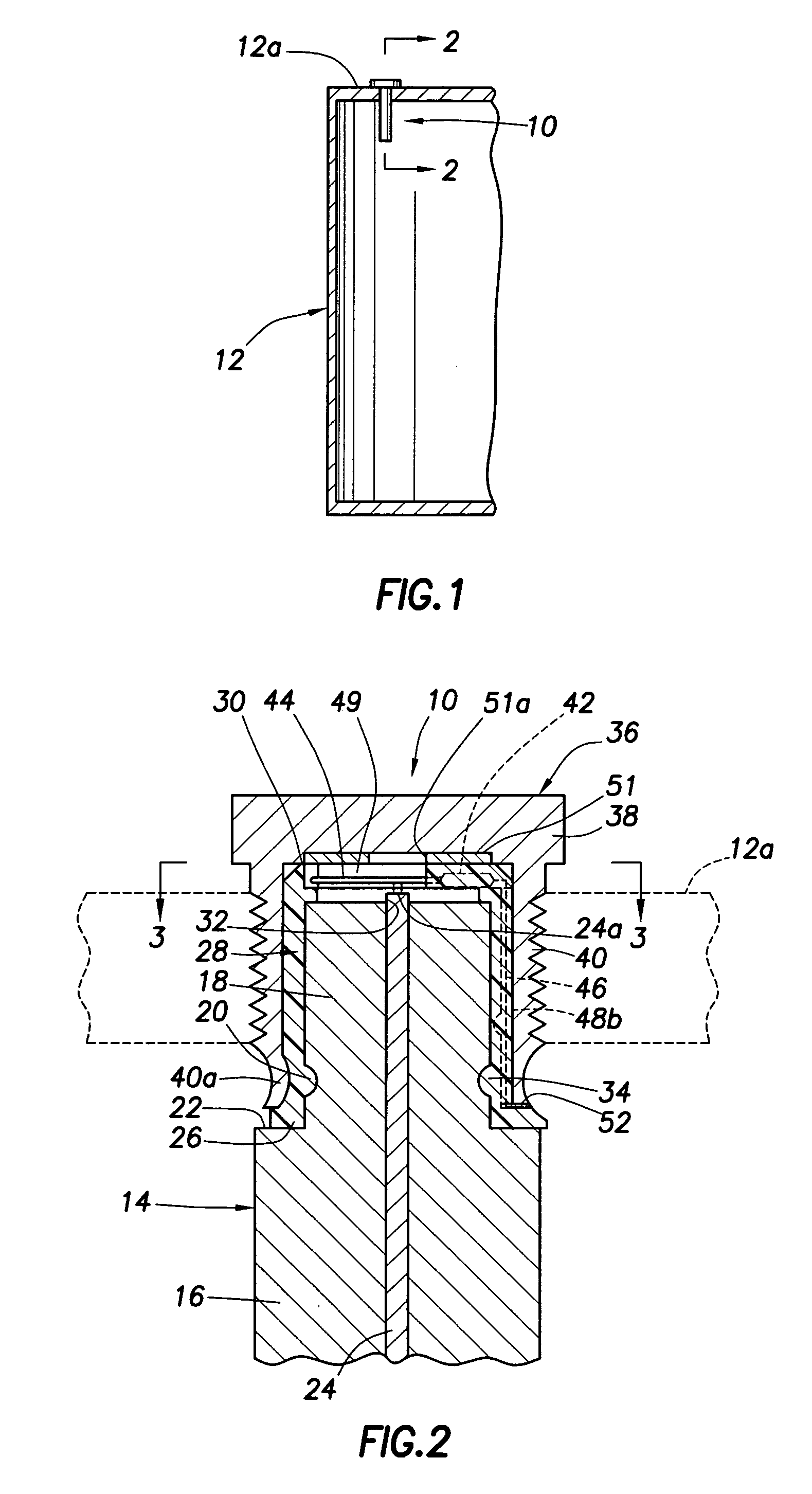
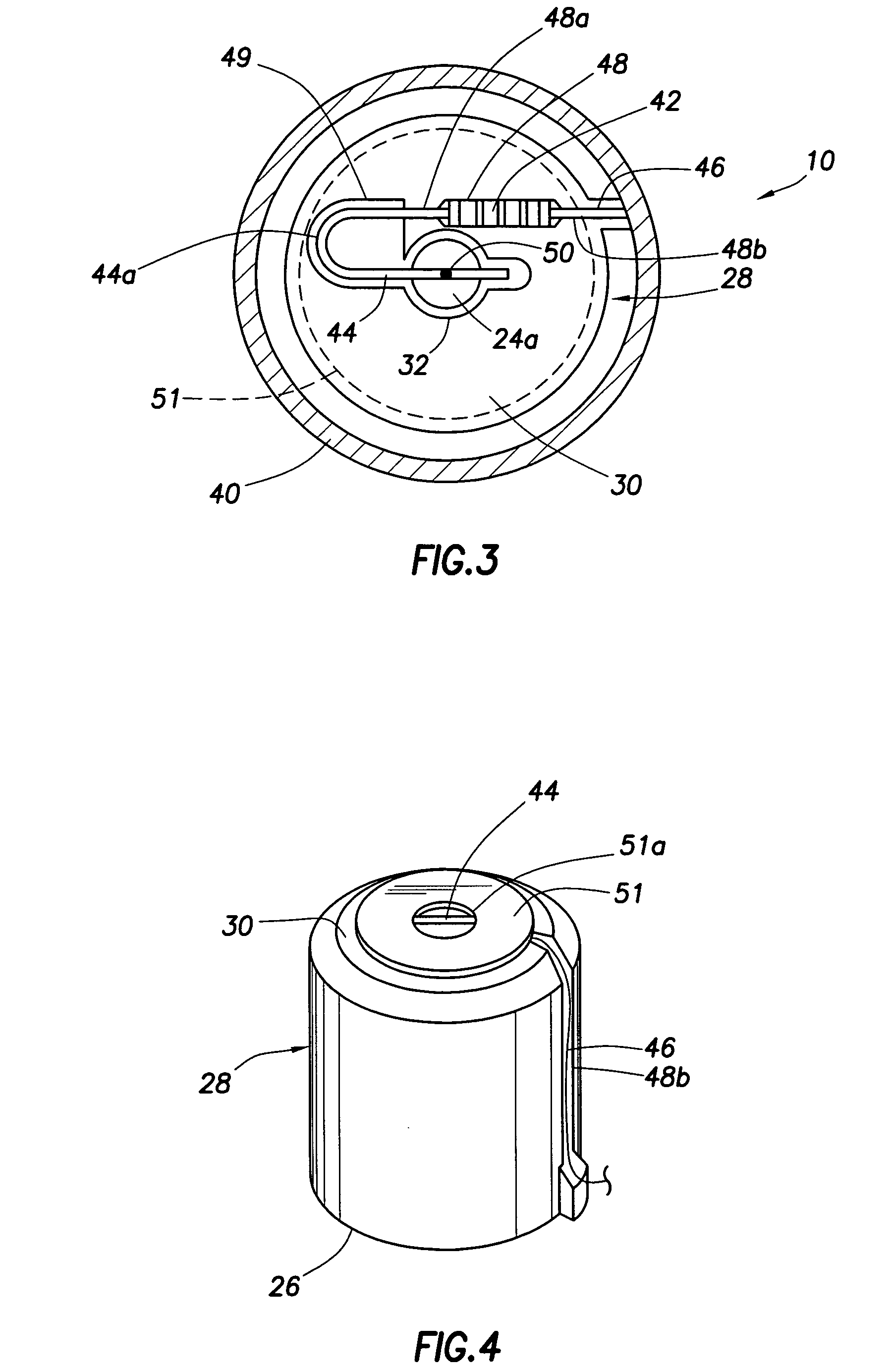
[0021] Referring to FIGS. 1-4, the present invention provides a specially designed resistored sacrificial anode assembly 10 which is similar to, but provides substantial improvements over, the sacrificial anode assembly illustrated and described in U.S. Pat. Nos. 5,256,267 and 5,334,299 which have been incorporated by reference herein in their entireties.

[0022] The resistored sacrificial anode assembly 10 is operatively installed in the top end wall 12a of a representative metal water heater storage tank 12, extends into the water-filled interior of the tank, and operates to cathodically inhibit corrosion of the tank. AS cross-sectionally illustrated in FIG. 2, the anode assembly 10 includes a cylindrically shaped sacrificial anode member 14 having a main body portion 16, a reduced diameter neck portion 18 having an annular external side surface indentation 20 formed therein, and an annular ledge 22 formed at the juncture of the main body and neck portions 16,18. Axially extending cen


PUM

PropertyMeasurementUnit
Electrical conductoraaaaaaaaaa
Plasticityaaaaaaaaaa
Stress optical coefficientaaaaaaaaaa

Abstract

A sacrificial anode assembly operative to inhibit corrosion in the metal tank portion of a water heater includes a cylindrical metal anode member having an end retained within a tubular, electrically non-conductive plastic insulating sleeve which, in turn, is captives retained within a metal cap portion of the assembly. A resistor is received in an end surface groove of the sleeve and has a lead wire spot-welded or soldered to a core wire portion of the anode member. To prevent contact between the lead wire and the metal cap, and to protect the lead wire against vibration caused breakage at its spot weld or solder area, a U-shaped central portion of the lead wire is received in a through-opening in the resistor-supporting end of the sleeve which is covered by an annular insulating wafer formed from an electrically non-conductive material.

Description


Claims


Application Information

Patent Timeline
Owner RHEEM MFG CO
Why Eureka
Try Eureka