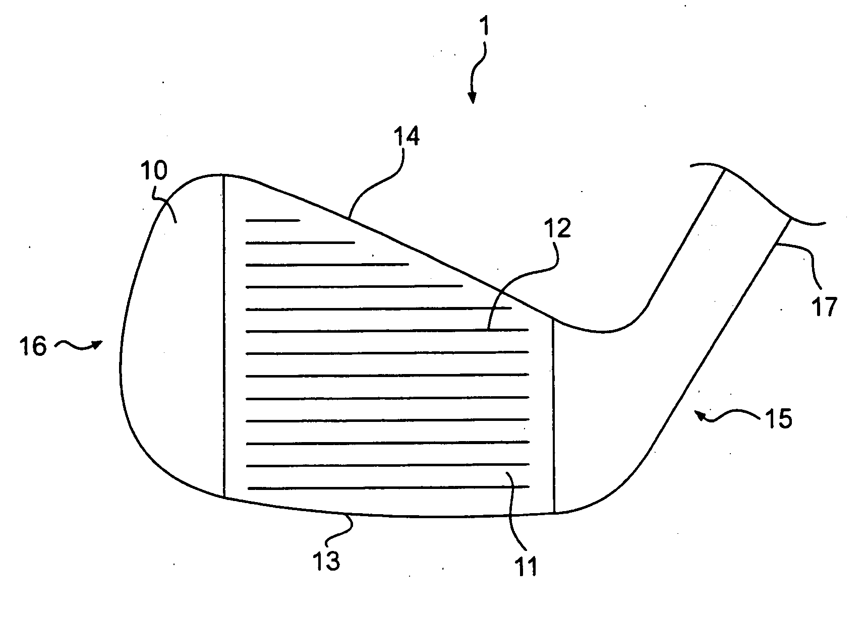
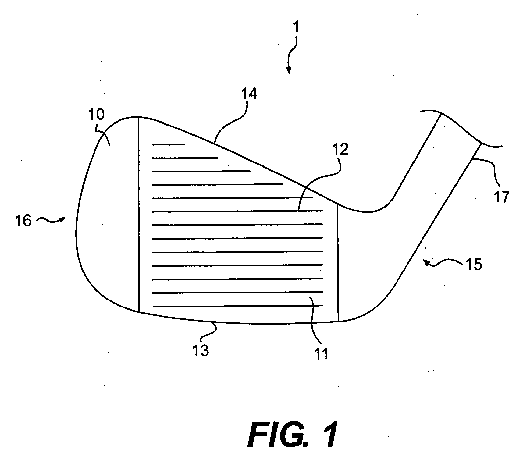
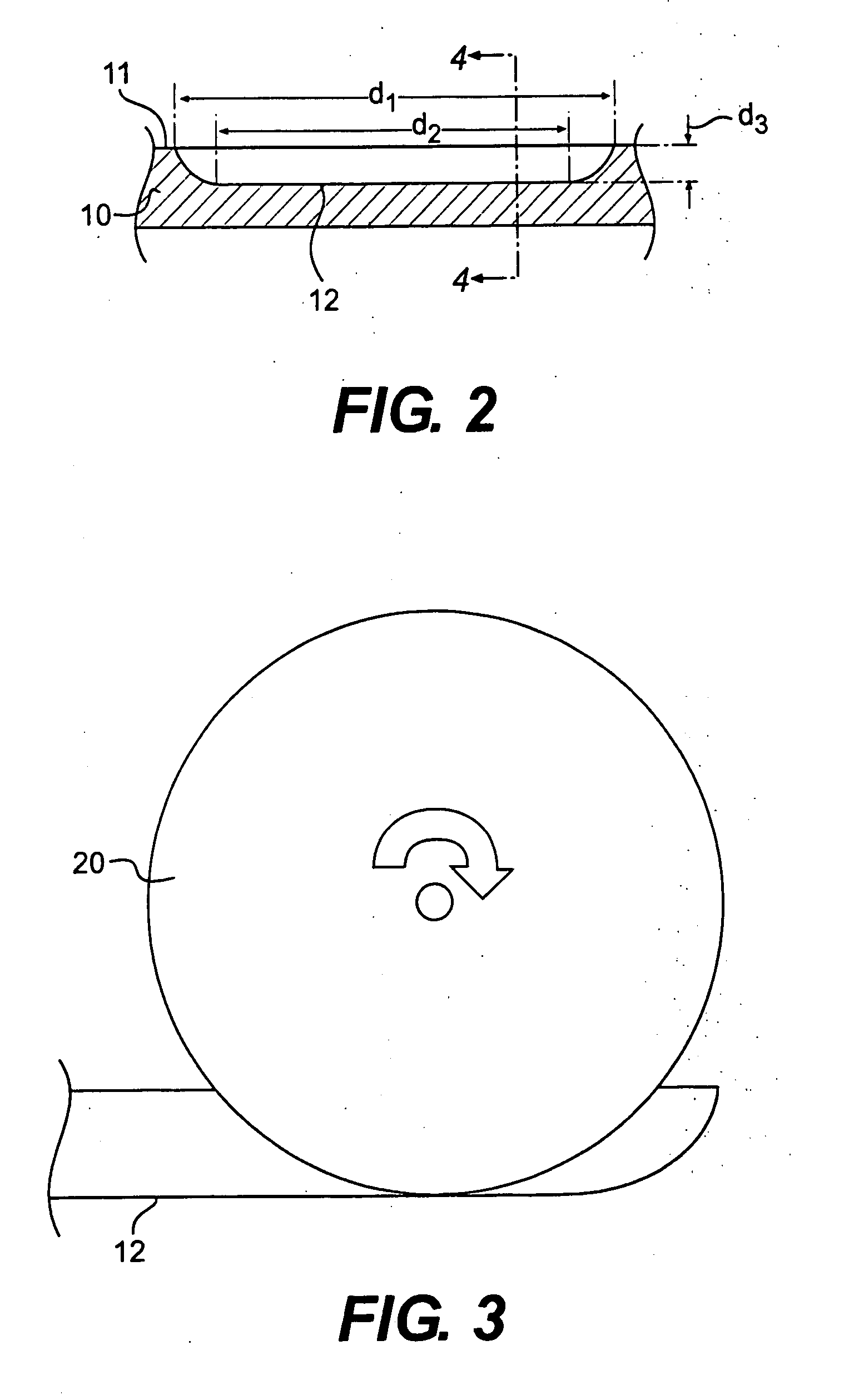
Golf club head groove configuration

a golf club and groove technology, applied in the field of golf clubs, can solve problems such as inconsistency along the length of the groove, and achieve the effects of tightening the tolerance, tightening the draft angle, and increasing the production ra

Active Publication Date: 2007-06-28
ACUSHNET CO
View PDF21 Cites 70 Cited by
  • Summary
  • Abstract
  • Description
  • Claims
  • Application Information

AI Technical Summary

Benefits of technology

This patented groove design helps improve the performance of golf balls by making them smoother and easier to roll over. It also makes it stronger and longer-lasting compared to traditional methods like castings or forgings. Grooves can be made using various techniques such as spinning or flying saws. They should have a tight draft angle between 0-5 degrees and 12-15 degrees, which means they shouldn't be too sharp at these points.

Problems solved by technology

The technical problem addressed by this patent is how to improve the performance of iron-type golf club heads without sacrificing their appearance.

Method used


Image

  • Golf club head groove configuration
  • Golf club head groove configuration
  • Golf club head groove configuration

Examples


Embodiment Construction

[0024] Other than in the operating examples, or unless otherwise expressly specified, all of the numerical ranges, amounts, values and percentages such as those for amounts of materials, moments of inertias, center of gravity locations, loft and draft angles, and others in the following portion of the specification may be read as if prefaced by the word “about” even though the term “about” may not expressly appear with the value, amount, or range. Accordingly, unless indicated to the contrary, the numerical parameters set forth in the following specification and attached claims are approximations that may vary depending upon the desired properties sought to be obtained by the present invention. At the very least, and not as an attempt to limit the application of the doctrine of equivalents to the scope of the claims, each numerical parameter should at least be construed in light of the number of reported significant digits and by applying ordinary rounding techniques.

[0025] Notwithsta


PUM


Abstract

The present invention is directed to a golf club head with an improved striding surface. The grooves are machined into the strike surface with tight tolerances. The grooves have sharp edges, radiused ends, and a draft angle between about 2° and 12°. The striking face is machined such that it has a uniform texture with a roughness of more than 40 Ra. The grooves may contain a plurality of portions, including a radiused or angled portion, a portion having substantially parallel walls, a portion having a v-shape, and a curved portion.

Description


Claims


Application Information

Patent Timeline
Owner ACUSHNET CO
Why Eureka
Try Eureka