Heating coil, heating apparatus and manufacturing method of workpiece

Pending Publication Date: 2021-07-01
NETUREN CO LTD
View PDF3 Cites 0 Cited by
  • Summary
  • Abstract
  • Description
  • Claims
  • Application Information

AI Technical Summary

Benefits of technology

[0004]Illustrative aspects of the present invention provide a heating coil that is capable of reducing or preventing local overheating in a pe

Problems solved by technology

Heating methods described in JP2001-152242A and JP2001-192734A require a large number of plugs for the induction heating of a large amount of workpieces and r

Method used


Image

  • Heating coil, heating apparatus and manufacturing method of workpiece
  • Heating coil, heating apparatus and manufacturing method of workpiece
  • Heating coil, heating apparatus and manufacturing method of workpiece

Examples


Embodiment Construction

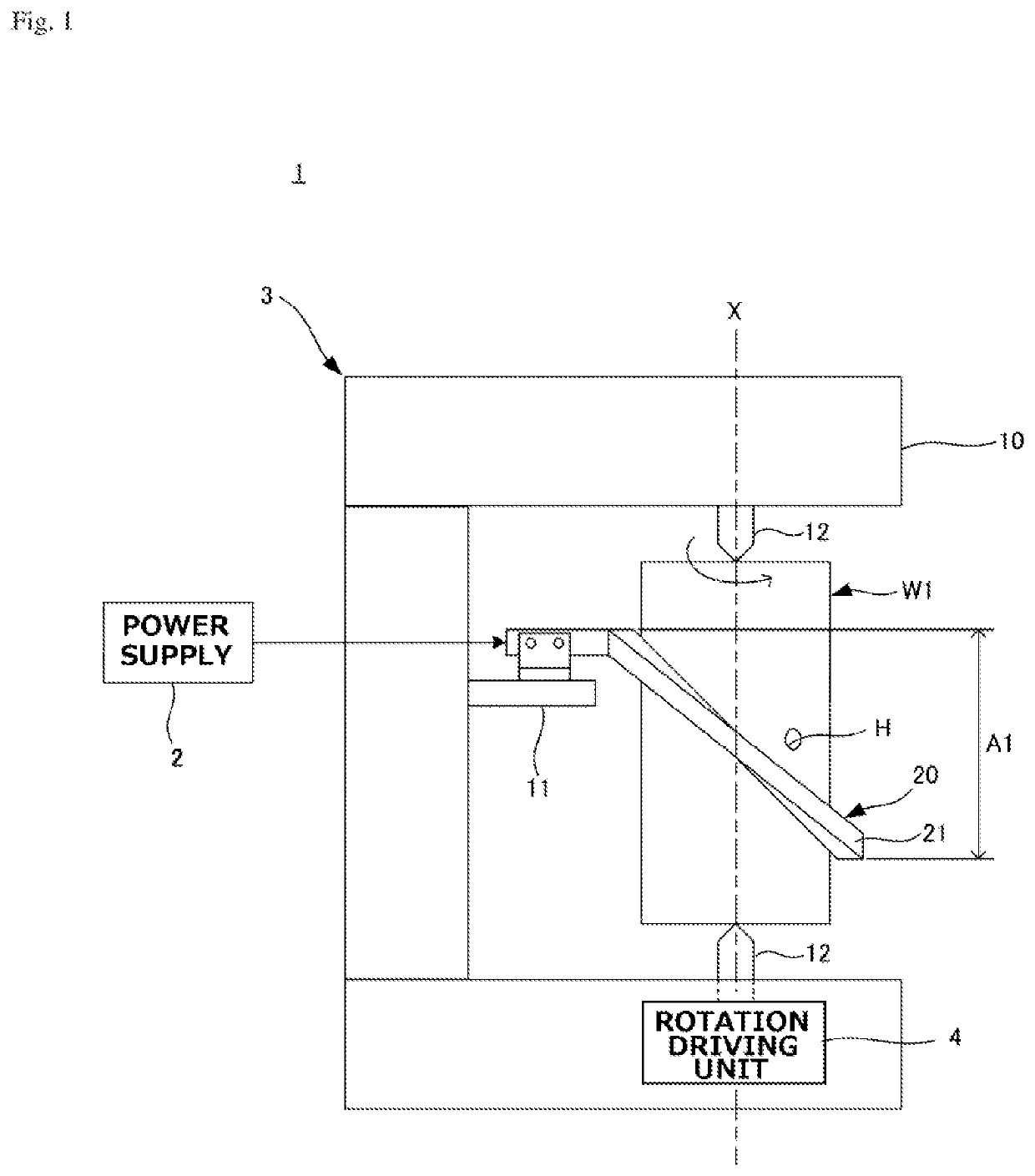
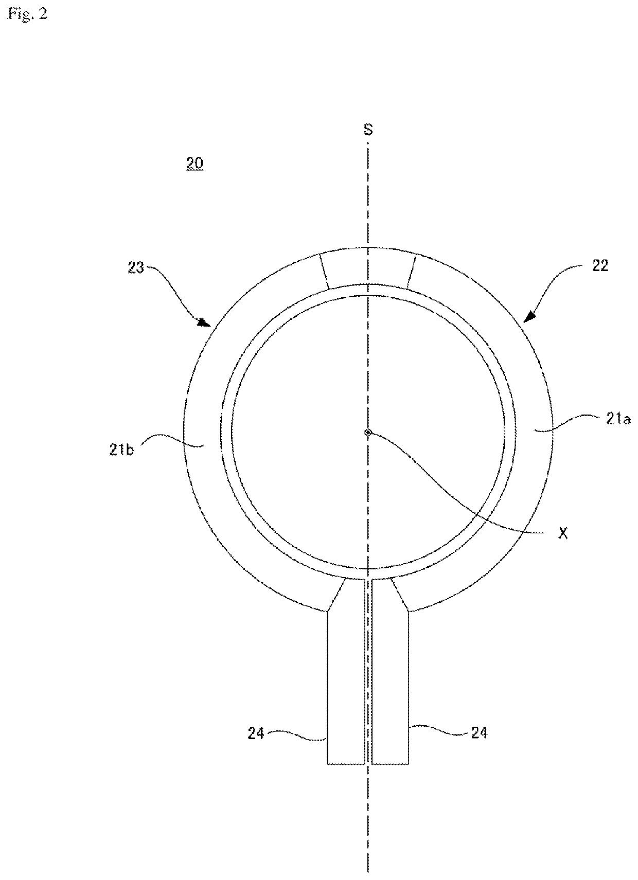
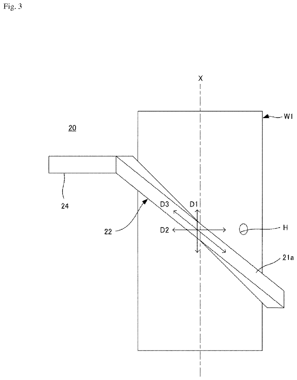
[0025]FIG. 1 schematically illustrates an example of a heating coil and a heating apparatus for illustrating an embodiment. FIGS. 2 to 4 illustrate the heating coil in FIG. 1.

[0026]A heating apparatus 1 is a stationary heating apparatus that is configured to inductively heat an outer peripheral surface of a cylindrical workpiece W1. A hole H extending in a radial direction from the outer peripheral surface is formed in the workpiece W1. The hole H may be a through hole or a blind hole.

[0027]The heating apparatus 1 includes a heating coil 20 that is configured to inductively heat the outer peripheral surface of the workpiece W1, a power supply 2 that is configured to supply high frequency AC power to the heating coil 20, a supporting portion 3 that is configured to support the workpiece W1 and the heating coil 20, and a rotation driving unit 4 that is configured to rotate the workpiece W1 about a central axis X of the workpiece W1.

[0028]The heating coil 20 is configured such that a cond


PUM


Abstract

A heating coil is configured to induction heat a workpiece having a hole. The heating coil includes first and second heating units respectively having conductors. The conductors of the first and second heating units extend in inclination directions intersecting an axial direction and a circumferential direction of an outer peripheral surface of the workpiece.

Description


Claims


Application Information

Patent Timeline
Owner NETUREN CO LTD
Why Eureka
Try Eureka