Threaded implant with improved distal end

Inactive Publication Date: 2007-07-12
LEVISMAN RICARDO
View PDF19 Cites 8 Cited by
  • Summary
  • Abstract
  • Description
  • Claims
  • Application Information

AI Technical Summary

Benefits of technology

[0017] It is still another object of the present invention to provide a dental implant with improved cutting distal end comprising an implant body having a head for receiving a dental prosthesis and a root for anchoring into a bone of a patient, wherein the root is diagonally truncated at a distal portion thereof to form an inclined cutting face.
[0018] It is a further object of the present invention to provide a dental implant with improved cutting distal end comprising an implant body having a head for receiving a dental prosthesis and a root for anchoring into a bone of a patient, wherein the root is diagonally truncated at a distal portion thereof to form an inclined sharp cutting face extending diagonally across the root and asymmetrically relative to a longitudinal geometrical axis of the implant, whereby the cutting face extends from a distal end of the root at one l

Problems solved by technology

Another problem or difficulty is that when the implant must be installed into the bone bore the length of the implant must be in agreement to the depth of the bore or socket.
However, this is not an easy task.
If the implant is screwed into the bone and it results stagnated or -firmly anchored against the lateral walls of the bore without reaching and contacting the bottom of the bore, the implant would result in an improper installation with the future disassembling consequences.
However, while the implantologist or dentist becomes aware of the misfit and deficient installation generally he/she are not able to remove the implant as long as it has already been firmly wedged into the bore and, if stronger forces are applied onto the implant to remove it from the bore it is quite frequent that the implant body is broken with a part thereof remaining into the bore and with the drastic consequences this may imply.
These difficulties increase as long as the outer surfaces of the implants are provided with means for enhancing osseous integration such as outer surface textures, pores, etc. which causes a problem in the displacement of the implant.
When the smooth rounded end of the implant body does not contacts the bottom of the socket the threads at the upper or proximal portion of the body do not get enough anchoring against the socket walls.
While an oversized hole depth of about 2 mm serves to more easily position a tapered implant at the cor

Method used


Image

  • Threaded implant with improved distal end
  • Threaded implant with improved distal end
  • Threaded implant with improved distal end

Examples


Embodiment Construction

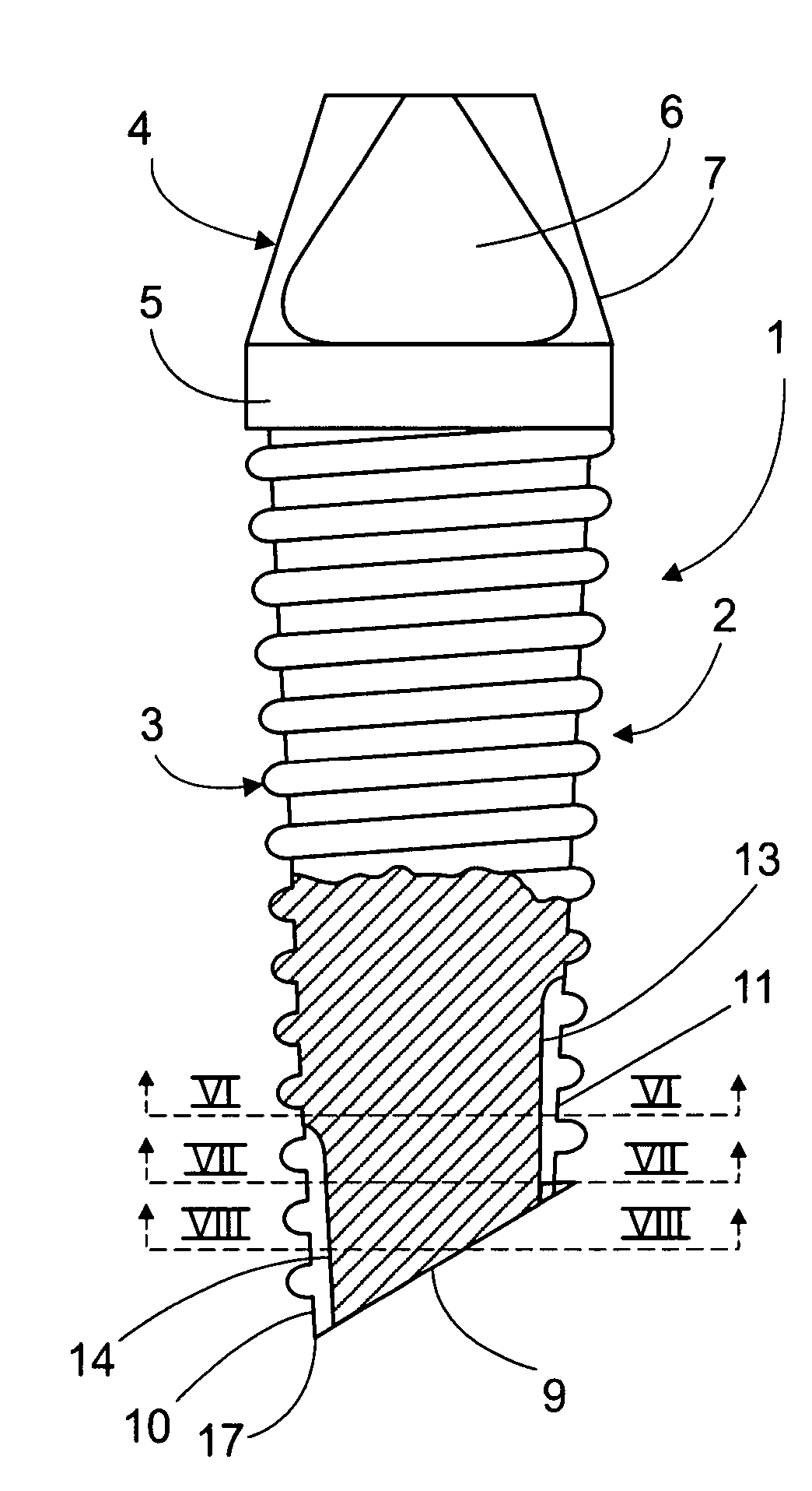
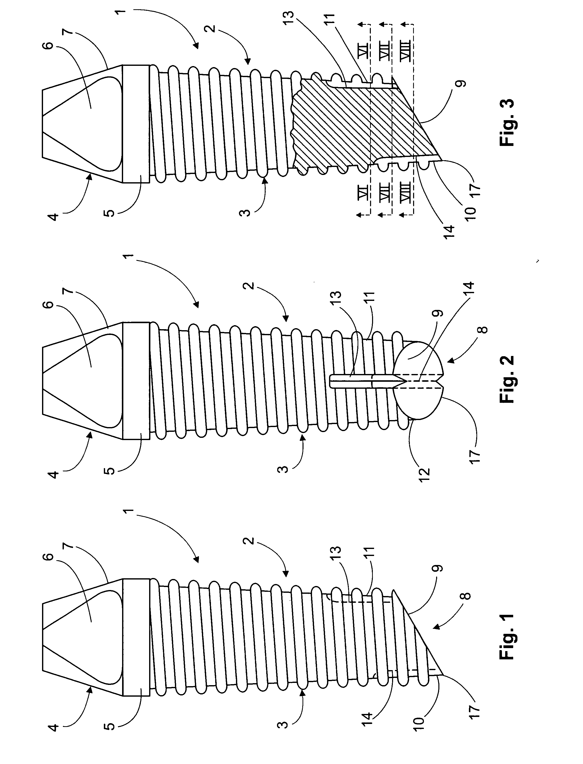
[0028] Now referring in detail to the invention, the dental implant according to the invention comprises an implant body 1 with a root portion 2 generally of a conical or tapered shape including a plurality of threads 3 and a head portion or head 4, preferably having a frustoconical profile as disclosed in U.S. Ser. No. 11 / 012,931 to the same inventor of the present application and the contents of which are included as a reference in the present application. The implant body with its corresponding portions is made preferably of a bio-compatible material, such as a metal, more preferably titanium and most preferably titanium that is chemically treated, for example by an osseous conductive substance, to have an outer surface for promoting the osseous integration of the implant into the patient's bone. Root portion 2 and head portion 4 are preferably separated by a collar portion 5, preferably a cylindrical body portion, free of threads. Threads 3 may be of any convenient and / or desir


PUM


Abstract

A dental implant with improved cutting distal end for preventing the implant from stagnating along a bone socket during implantation includes an implant body having a head for receiving a dental prosthesis and a root for anchoring into a bone of a patient; wherein the root is truncated at a distal portion thereof to form an inclined sharp cutting face.

Description


Claims


Application Information

Patent Timeline
Owner LEVISMAN RICARDO
Why Eureka
Try Eureka