Device & Method for the Reduction of Emissions

a technology of emission reduction and device, applied in the direction of colloidal chemistry, machine/engine, separation process, etc., can solve problems such as environmental pollution, and achieve the effects of curbing alarming effects, reducing environmental pollution, and improving life conditions

Inactive Publication Date: 2008-03-06
SABERTEC LLC
View PDF7 Cites 8 Cited by
  • Summary
  • Abstract
  • Description
  • Claims
  • Application Information

AI Technical Summary

Benefits of technology

This patented technology helps decrease harmful gaseous substances released during engine operation while improving air purification efficiency. It also reduces damage to our natural resources like water supplies or crops due to these gases being discharged into space around us.

Problems solved by technology

The technical problem addressed in this patented text relates to improving the performance and cost savings associated with diesel engines without compromising their safety fidelity due to increased particulate content in gas mixtures released into the cabin occupied by cars. Existing solutions involve adding filters to reduce particle size but may lead to insensitive values like NOx. Additionally, some attempts were proposed to solve this issue by controlling the negative pressures applied to the intake manifold. However, none provide sufficient feedback to ensure safe driving behavior despite increasing load and decreasing fuel usage.

Method used


Image

  • Device & Method for the Reduction of Emissions
  • Device & Method for the Reduction of Emissions
  • Device & Method for the Reduction of Emissions

Examples


Embodiment Construction

[0036] The present invention provides an efficient device and method for reducing the emission of harmful gases in the environment, reducing noise, reducing the consumption of fuel, and improving an engine's performance, all in a cost effective manner. The engine may be any form of combustion engine such as, for example, an engine in a car, truck, lawnmower, or other vehicle or device. The making and using of the presently preferred embodiments are discussed in detail below. It should be appreciated, however, that the present invention provides many applicable inventive concepts that can be embodied in a wide variety of specific contexts. The specific embodiments discussed are merely illustrative of specific ways to make and use the invention, and do not limit the scope of the invention.

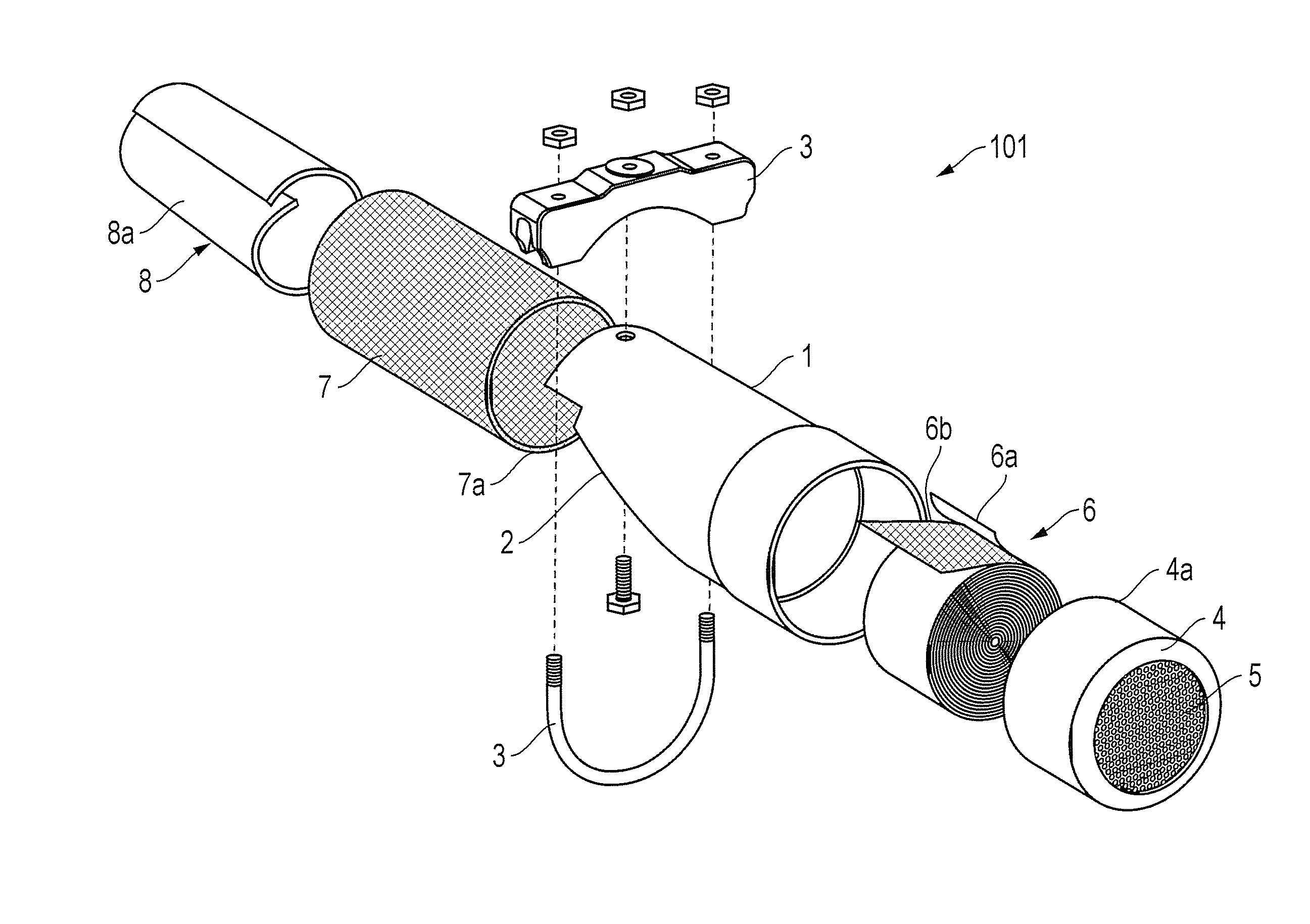
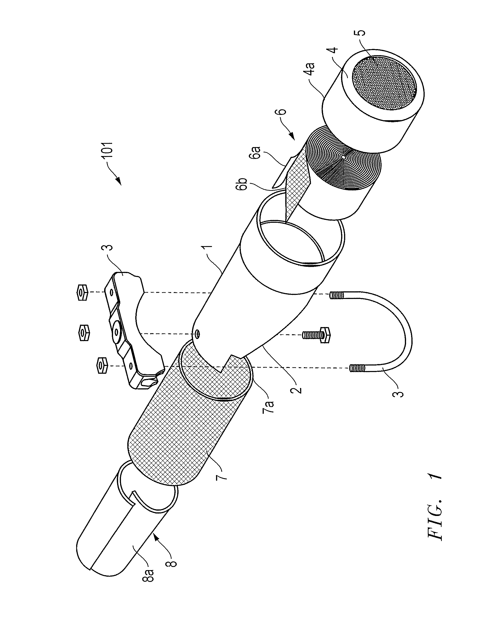
[0037] Referring now to the drawings, FIG. 1 shows one embodiment of the device 101 comprising a cylindrical carcass 1 with a beveled opening 2 in a diagonal line in its proximal part where it is fixed


PUM

PropertyMeasurementUnit
Electrical conductoraaaaaaaaaa
Perimeteraaaaaaaaaa

Abstract

An emission reduction device which may be removably affixed to an engine's exhaust system. The device comprises a cylindrical carcass with a beveled opening in a diagonal line in its proximal part A bobbin is affixed in the distal portion of the carcass. A cylindrical-shaped fibrous blanket may be inserted in the carcass and the fibrous blanket may be wrapped in a wire mesh. A second fiber mesh formed into a cone may be removably inserted in the cylindrical-shaped fibrous blanket with the larger diameter of the cone positioned proximally.

Description


Claims


Application Information

Patent Timeline
Owner SABERTEC LLC
Why Eureka
Try Eureka