Apparatus and methods for securing together bone fragments

a technology of bone fragments and stents, applied in the field of stents and methods for securing together bone fragments, can solve the problems of sternal dehiscence, limited strap tension, and not always being a good strap conformity

Inactive Publication Date: 2014-04-10
NEOS SURGERY SL
View PDF5 Cites 17 Cited by
  • Summary
  • Abstract
  • Description
  • Claims
  • Application Information

AI Technical Summary

Benefits of technology

The present device described by this patented technology allows two parts (bone pieces) with different shapes to be securely joined without any gap left therebetween during use. This makes it easier to put them into place correctly on their owners' body after surgery while still maintaining stability.

Problems solved by technology

Technicians used during these past years were able to join sections of sternums without causing any issues related to lack of proper fit. However, current solutions require multiple steps involving cutting off pieces from the sternrum itself, making them less efficient than desired. Additionally, previous designs had limitations regarding how well they could adapt themselves to different types of bones.

Method used


Image

  • Apparatus and methods for securing together bone fragments
  • Apparatus and methods for securing together bone fragments
  • Apparatus and methods for securing together bone fragments

Examples


Embodiment Construction

[0041]Throughout this disclosure the discussion will be primarily directed to the joining together of sternum bone fragments. It is to be appreciated, however, that the devices and methods disclosed herein are applicable to the joining together of bone fragments other than those of the sternum.

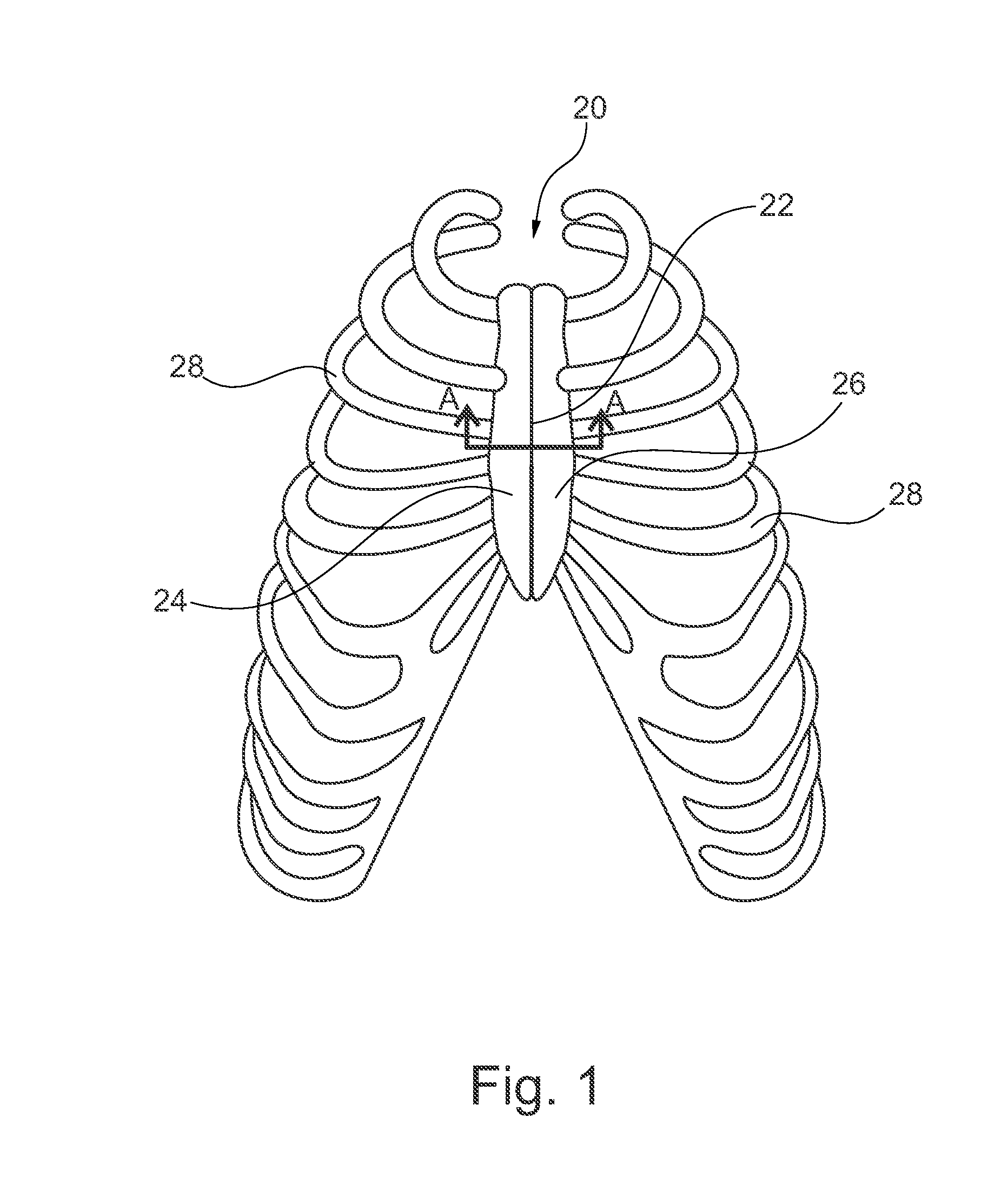
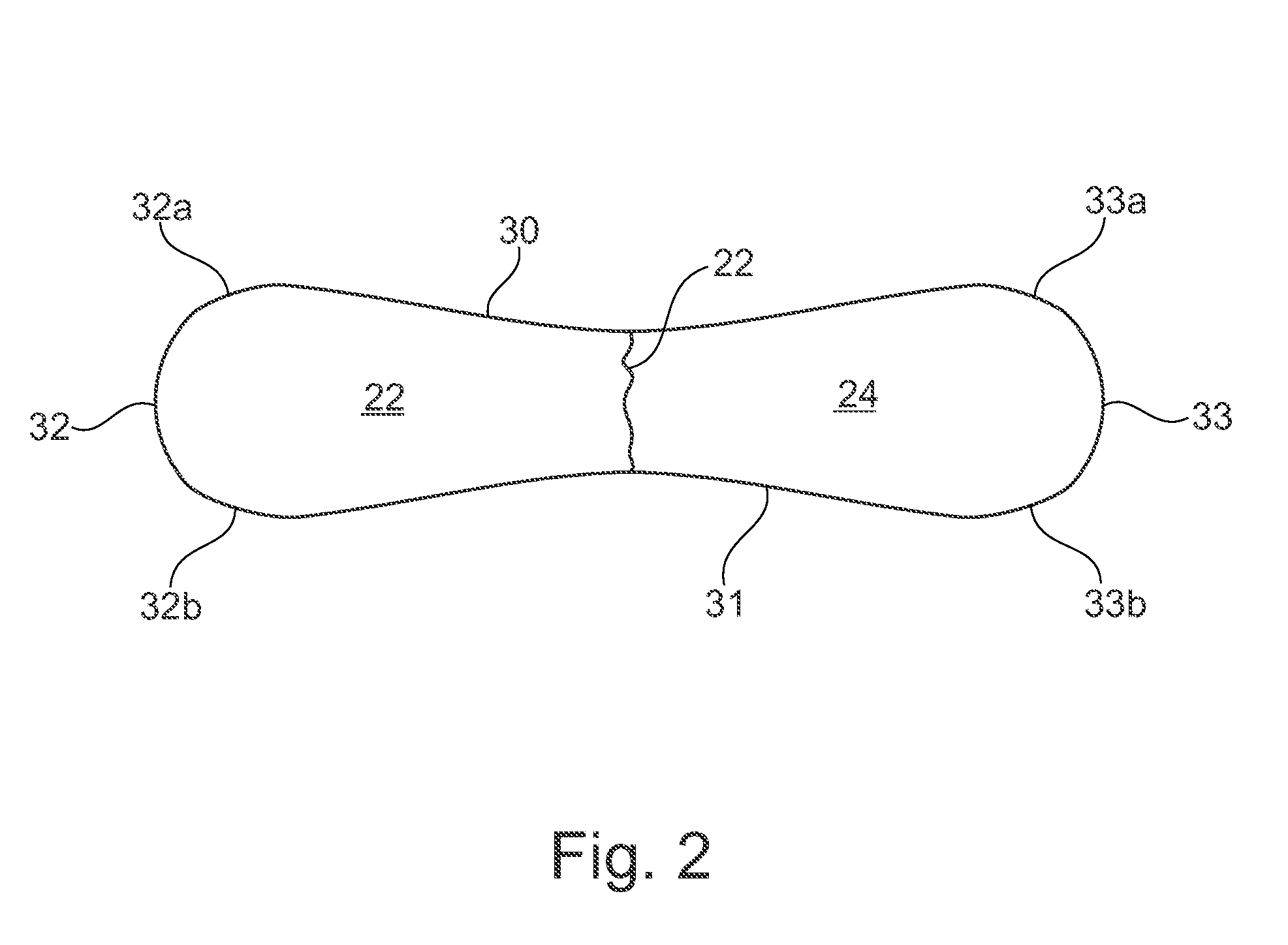
[0042]FIG. 2 illustrates a cross-section view along line A-A of FIG. 1 with the sternum having a cut 22 that divides it into the sternum halves 22 and 24. The cross-sectional shape of the sternum generally comprises elongate top and bottom surfaces 30 and 31 that are joined at their ends by first and second bent surfaces 32 and 33. The top and bottom surfaces 30,31 typically possess some curvature as shown in FIG. 2, but generally appear relatively flat in nature as compared to the bent ends 32,33 that possess a large degree of curvature along a short distance. As shown in FIG. 2, in some patient's the top surface 30 may have a generally concave shape and the bottom surface 31 may have a generall


PUM


Abstract

An apparatus for securing together first and second bone segments having peripheral surfaces comprising one or more bends. In some implementations the fixation device includes an elongate flexible strap having a proximal end and a distal end, the elongate flexible strap having a plurality of ratchet teeth disposed along an elongate distal portion thereof that function with a ratchet member within a locking head situated at the proximal end to permit the formation of a closed loop about the bone fragments. In some implementations the elongate flexible strap has a first elongate portion situated between the locking head and the elongate distal portion, the first elongate portion of the elongate flexible strap being more flexible than the elongate distal portion of the elongate flexible strap, the first elongate portion configured to extend across at least one of the one or more bends when the apparatus is in a secured state.

Description


Claims


Application Information

Patent Timeline
Owner NEOS SURGERY SL
Why Eureka
Try Eureka