Downhole/openhole anchor

Active Publication Date: 2007-08-02
BAKER HUGHES INC
View PDF13 Cites 7 Cited by
  • Summary
  • Abstract
  • Description
  • Claims
  • Application Information

AI Technical Summary

Benefits of technology

[0007] A whipstock/billet anchor can be set in open hole such that one or more slips initially shift laterally near the lower end or below the whipstock/billet/billet while the upper end reacts and gets pushed against the wellbore. Then with the top of the whipstock/billet/billet against the wellbore another slip gets a bite to secur

Problems solved by technology

When the drill bit was advanced to drill the lateral its interaction with the top of the whipstock/billet/billet that was unsupported by the surrounding well bore can cause vibration on the anchor slips causing them lose the grip on formation.
As a result the whipstock/billet/billet was without support and could slip down the well bore.
At that point drilling had to stop a sidetrack has to be done above the whipstock/billet/billet process

Method used


Image

  • Downhole/openhole anchor
  • Downhole/openhole anchor
  • Downhole/openhole anchor

Examples


Embodiment Construction

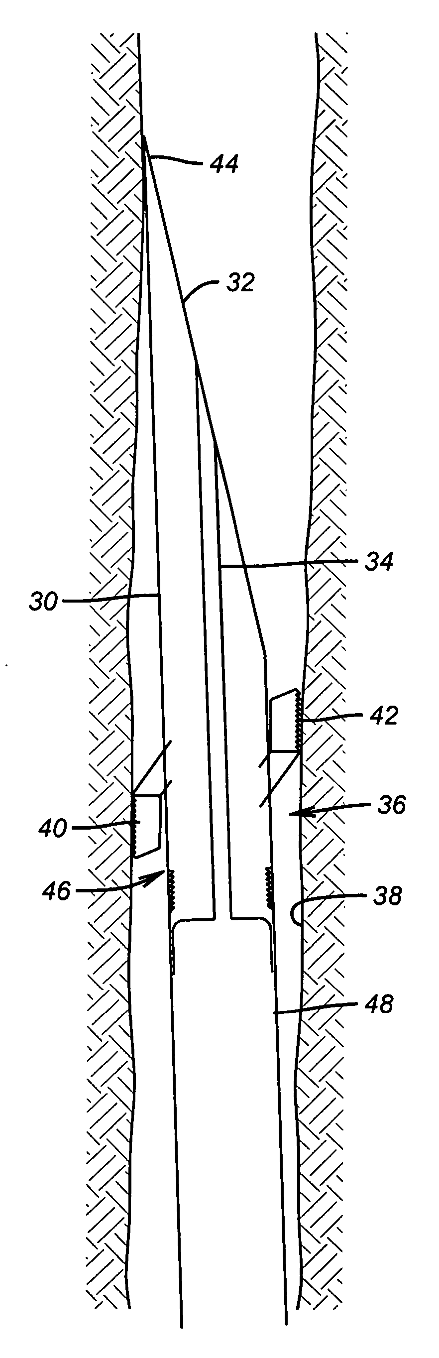
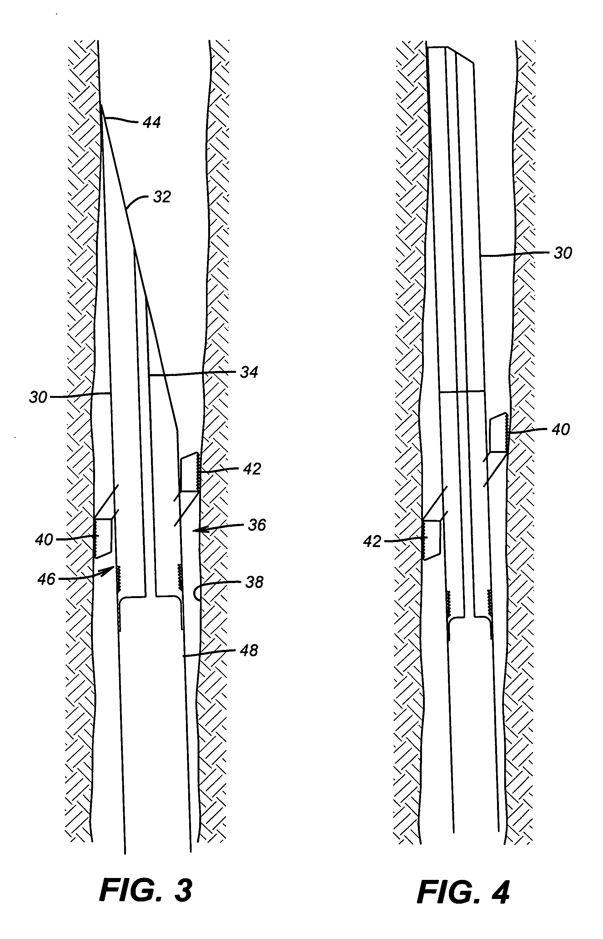
[0015] The overall assembly is best seen in FIG. 3. There a whipstock / billet 30 has a tapered face 32 and a through passage 34 through which a setting tool (not shown) is initially extending for setting the anchor 36 in borehole 38. Anchor 36 preferably has lower slip sets 40 of which only one is shown and at least one upper slip set 42. Preferably when there are two slip sets 40 and an upper slip set 42 the circumferential spacing among them is preferably about 120 degrees. This puts the lower slip sets 40 on one side of the anchor 36 with the upper slip set 42 on the other. In fact the angles of separation can vary with the idea being that the lower slips sets being on one half of the circumference and the upper slip sets on the other. The reason for this will be explained below.

[0016] Looking again at FIG. 3, showing the anchor 36 now set, it can be seen that the upper end 44 of the whipstock / billet 30 is pushed against the borehole 38. This happens when lower slip sets 40 push


PUM


Abstract

A whipstock/billet anchor can be set in open hole such that one or more slips initially shift laterally near the lower end or below the whipstock/billet while the upper end reacts and gets pushed against the wellbore. Then with the top of the whipstock/billet against the wellbore another slip gets a bite to secure the whipstock/billet in a manner where the wellbore gives it some support near its upper end as a drill bit engages the whipstock/billet to make a lateral. Open and cased hole application is contemplated. The anchor also allows running in and supporting a tubular string below and a tool above with the further option of cocking the tool for better support before securing it.

Description


Claims


Application Information

Patent Timeline
Owner BAKER HUGHES INC
Why Eureka
Try Eureka