Inverted-F antenna and mobile communication terminal using the same

Active Publication Date: 2007-11-15
SAMSUNG ELECTRO MECHANICS CO LTD
View PDF6 Cites 10 Cited by
  • Summary
  • Abstract
  • Description
  • Claims
  • Application Information

AI Technical Summary

Benefits of technology

[0015] The present invention has been made to solve the foregoing problems of the prior art and therefore an aspect of the present invention is to provide an antenna which is less susceptible to the changes in an external environment.

Problems solved by technology

In particular, as the conventional rod antenna and helical antenna protrude out of the terminal in a predetermined length, the likelihood of damage is increased when the terminal is dropped, which in turn degrades portability.
This kind of antenna structure, however, has a problem in that bending and mounting the antenna cause changes in the characteristics of the antenna since the signal line and the ground line are made separate from each other.
This mounting structure of the antenna is mainly focused on reducing the thickness of the terminal, but in practice, as the antenna mounting space occupies a relatively large area, the miniaturization of the terminal is limited.
Furthermore, as the antenna is installed in parallel with an RF board, the operation of the antenna is interfered by the terminal body or the metal portions (key pad assembly, LCD module, etc.) of the folder, hindering adequate antenna radiation characteristics.

Method used


Image

  • Inverted-F antenna and mobile communication terminal using the same
  • Inverted-F antenna and mobile communication terminal using the same
  • Inverted-F antenna and mobile communication terminal using the same

Examples


Example

[0038] Exemplary embodiments of the present invention will now be described in detail with reference to the accompanying drawings.

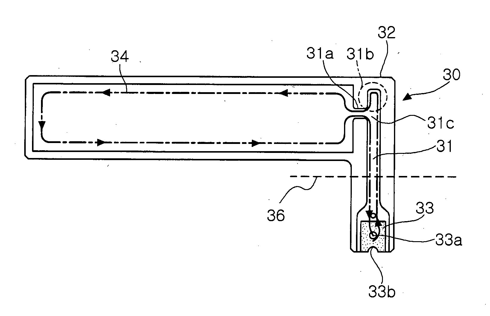
[0039]FIGS. 3a and 3b are plan views illustrating a planar antenna according to an embodiment of the present invention.

[0040] Referring to FIG. 3a, the planar antenna 30 according to an embodiment of the present invention includes a flexible board 32 with a radiation plate 34 and a signal line 31 formed thereon.

[0041] The signal line 31 includes a first end 31c connected to the radiation plate 34 via a connector 31a. In addition, the signal line 31 includes a second end 33 where a ground terminal 33a and a feed terminal 33b are formed. The ground terminal 33a is connected to a ground plate outside, and the feed terminal 33b is connected to a feed line outside.

[0042] The radiation plate 34 is connected vertically to the signal line 31.

[0043] At this time, a stub 31b is formed in the opposite direction from the extension direction of the signal line 31 fo


PUM


Abstract

An inverted-F antenna and a mobile communication terminal using the same. The antenna includes a flexible board and a radiation plate formed on the flexible board. The antenna further includes a signal line having a first end formed on the flexible board and connected to the radiation plate and a second end extending from the first end and provided as a connecting terminal for feeding and grounding. The mobile communication terminal includes an RF board, a ground plate formed on the RF board, a feed line formed on the RF board for supplying a signal, and the inverted-F antenna as described above.

Description


Claims


Application Information

Patent Timeline
Owner SAMSUNG ELECTRO MECHANICS CO LTD
Why Eureka
Try Eureka