Rack for containers

a technology for containers and racks, applied in the field of racks for holding objects, can solve the problems of relative movement, leakage of containers, and leaking containers, and achieve the effect of improving the stability and stacking of layers

Inactive Publication Date: 2008-04-10
REHRIG PACIFIC CO INC
View PDF50 Cites 17 Cited by
  • Summary
  • Abstract
  • Description
  • Claims
  • Application Information

AI Technical Summary

Benefits of technology

This invention relates to a device called a racker used by stores where items can be stored securely within them. It uses multiple rows of shelves arranged vertically along its sides connected together through column-like structures made up from metal tubes filled with foam material. These rowers have raised surfaces at their top ends to provide stable supports against tipping over during use. They also contain elastic parts like springs inside to make sure they stay tight when closed properly.

Problems solved by technology

This patented technical solution described in the current systems includes creating customized racks for carrying different types of products like water bottled goods (WC) and water tanks. However, these traditional methods require heavy equipment and materials, which makes it difficult to maintain consistently quality control over their use due to variations caused during manufacturing processes. Additionally, there may also occur issues where the raft does not fit well inside certain areas when being moved between compartments.

Method used


Image

  • Rack for containers
  • Rack for containers
  • Rack for containers

Examples


Embodiment Construction

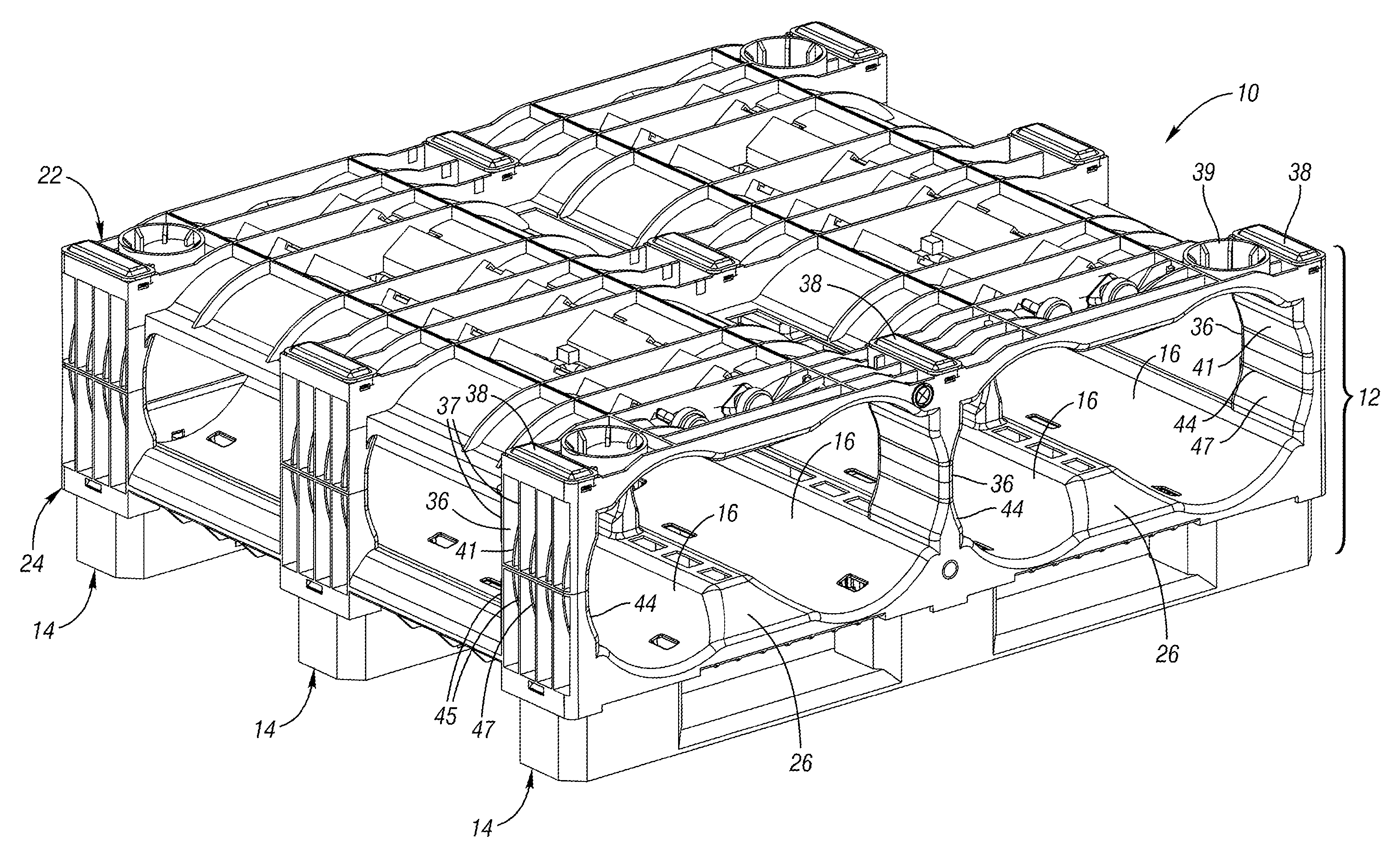
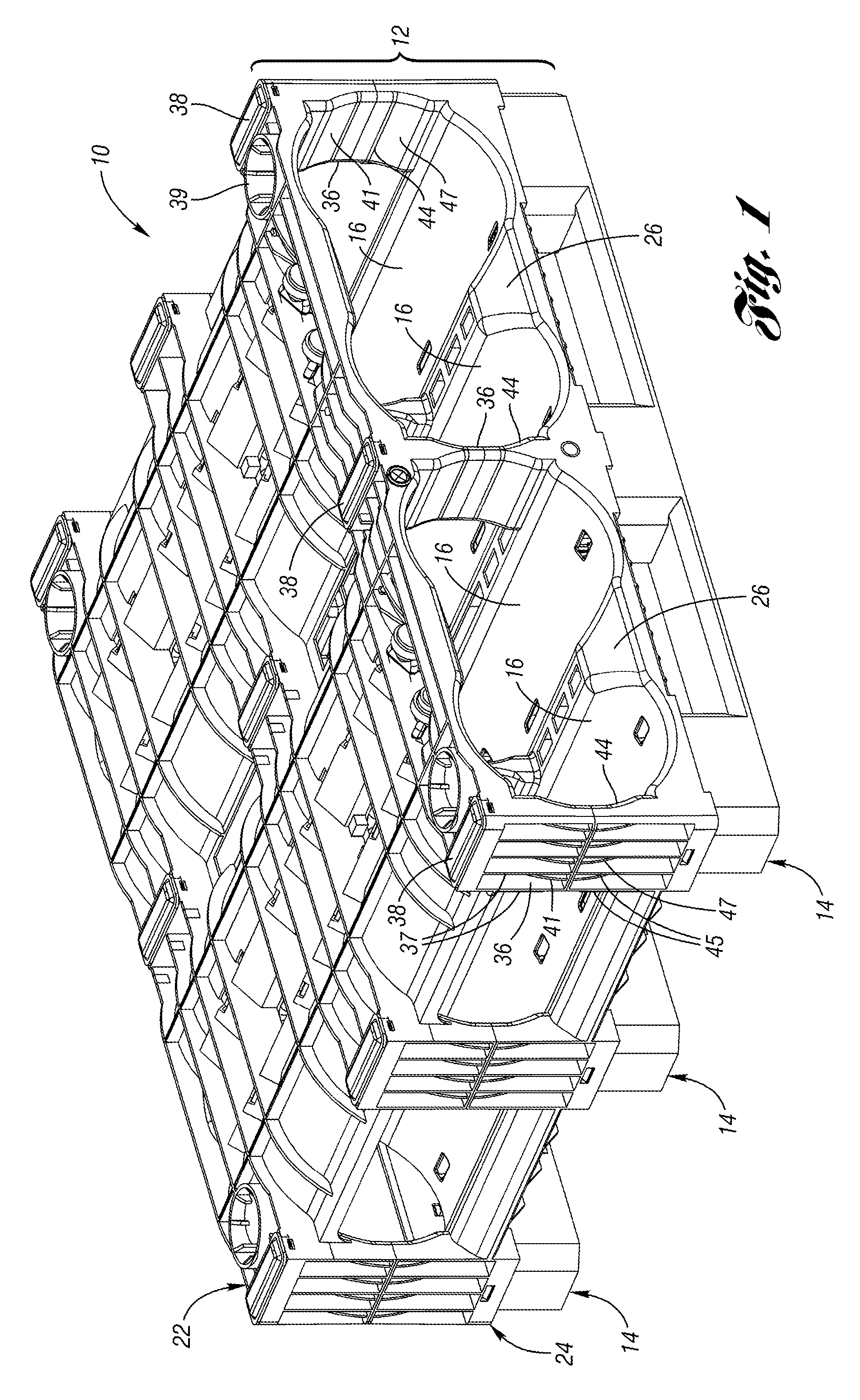
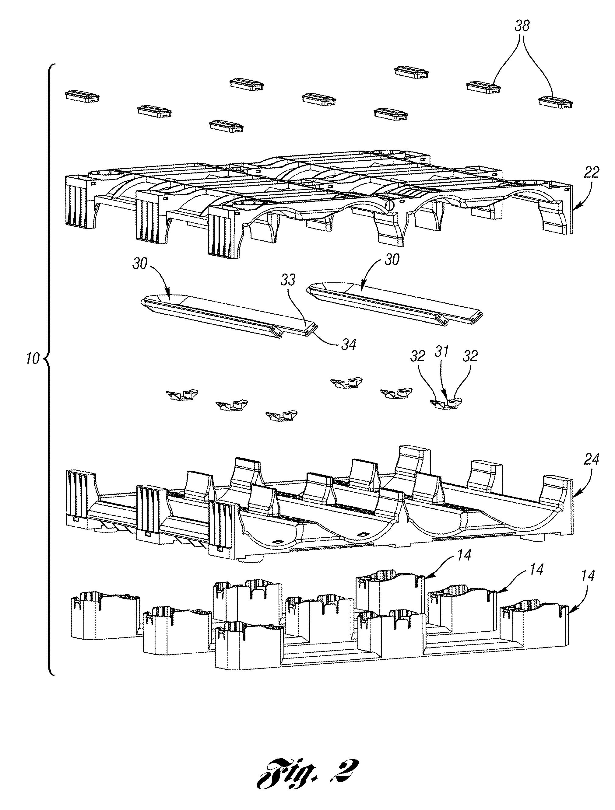
[0025]FIG. 1 is a perspective view of a rack 10 according to one embodiment of the present invention. The rack 10 includes a first layer 12 (or first “shelf”) supported on a plurality of supports 14. The first layer 12 defines a plurality of generally cylindrical bays 16. A pair of five gallon water bottles (not shown) can be received within each bay 16. The first layer 12 includes an upper section 22 and a lower section 24. The lower section 24 includes a partial divider 26 between each adjacent pair of bays 16.

[0026]The upper section 22 has a plurality (in this example, nine) of column portions 36, each having a support pad 38 thereon. In this example, the support pads 38 are tapered blocks snap fit to the top of the column portions 36. The support pads 38 ensure alignment of another layer stacked thereon, although the actual weight is transferred directly to the column portions 36, not on the support pads 38. The outer ones of the column portions 36 including a plurality of vertical


PUM


Abstract

A rack for securing containers includes a plurality of bays into which one or more containers are received. The rack includes an upper section and a lower section defining a bay therebetween. The bay has a concave support surface for supporting an object. A plurality of columns connect the upper section to the lower section. The upper section and the lower section each include a plurality of complementary interlocking members aligned with the plurality of columns, such that the interlocking members on the upper section would interlock with the interlocking members on the lower section of a similar rack stacked thereon. Each bay may include a resilient member, such as an expandable clamp or a resilient bumper.

Description


Claims


Application Information

Patent Timeline
Owner REHRIG PACIFIC CO INC
Why Eureka
Try Eureka