Syringe Cylinder

Inactive Publication Date: 2009-04-23
HISAMITSU PHARM CO INC
View PDF2 Cites 10 Cited by
  • Summary
  • Abstract
  • Description
  • Claims
  • Application Information

AI Technical Summary

Benefits of technology

[0018]As described above, the use of the syringe cylinder according to the present invention enables the intermediate

Problems solved by technology

Such an intermediate sliding stopper is subjected to significant friction in the syringe cylinder and thus has disadvantages such as an improper sliding operation.
However, if a vacuum tapping method such as the one described above is used to place the intermediate sliding stopper in the syringe cylinder of the conventional series sequential dispensation kit drug formulation, various problems may result from the cir

Method used


Image

  • Syringe Cylinder
  • Syringe Cylinder
  • Syringe Cylinder

Examples


Embodiment Construction

[0028]A preferred embodiment of the present invention will be described below in detail with reference to the drawings.

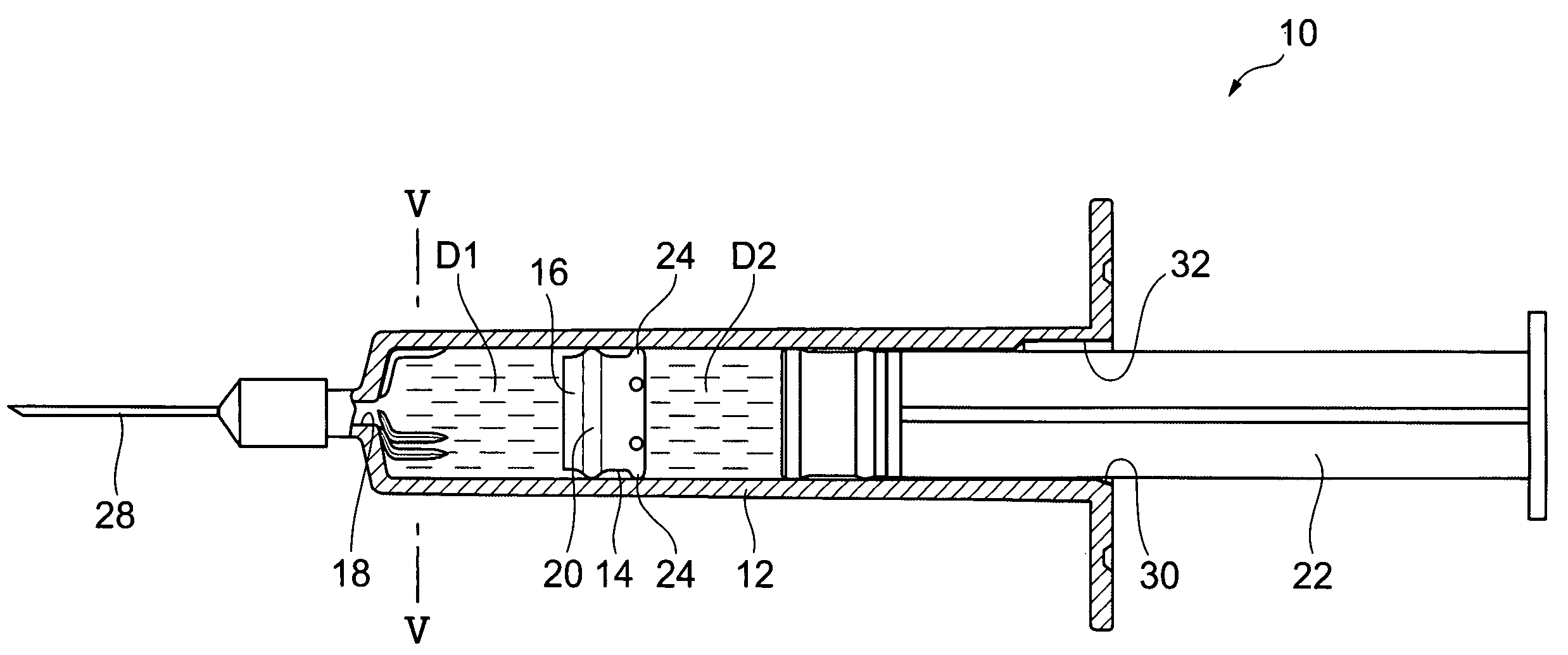
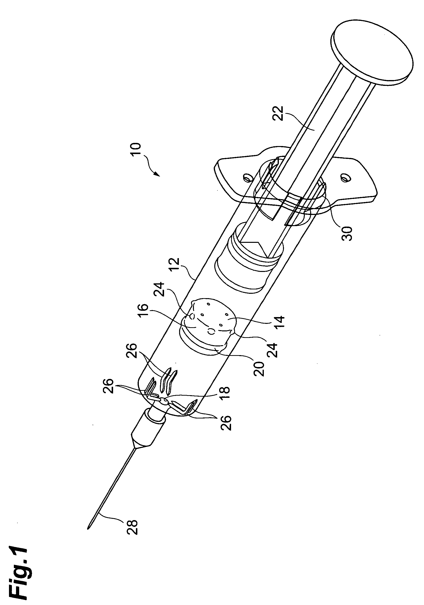
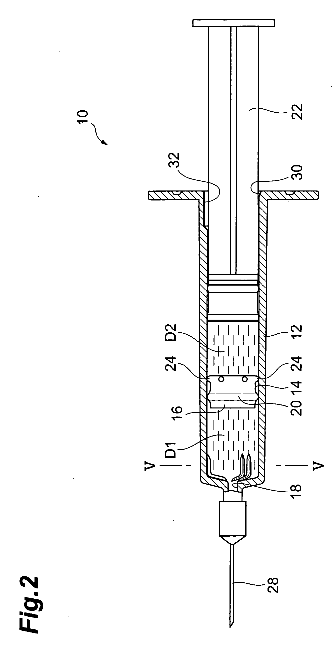
[0029]FIGS. 1 and 2 show a series sequential dispensation kit drug formulation 10 made up of a syringe cylinder according to the present invention. The illustrated kit drug formulation 10 is basically similar to the above-described conventional configuration. The kit drug formulation 10 includes an intermediate sliding stopper 14 inside a syringe cylinder 12. The intermediate sliding stopper 14 partitions the interior of the syringe cylinder 12 into two spaces in which different types of drugs D1 and D2 are filled.

[0030]The intermediate sliding stopper 14 is an integrally formed component obtained by subjecting surfaces of a rubber elastomer to silicon coating or Teflon (registered trademark) processing, for example. The intermediate sliding stopper 14 is composed of a substantially cylindrical main body portion 16, an annular lip portion 20 formed on a front end side


PUM


Abstract

A syringe cylinder 12 includes a groove 32 formed in an inner peripheral surface thereof and extending over a predetermined length from an opening end 30 thereof. Even with the intermediate sliding stopper 14 located at a position where the groove 32 is formed, the pressure inside the syringe cylinder 12 can be reduced. Thus, during vacuum tapping, the intermediate sliding stopper 14 can be held in the vicinity of the opening end 30 of the syringe cylinder 12. Consequently, the intermediate sliding stopper 14 can be inserted into the syringe cylinder 12 in a correct posture and reliably moved to a predetermined position in the syringe cylinder 12.

Description


Claims


Application Information

Patent Timeline
Owner HISAMITSU PHARM CO INC
Why Eureka
Try Eureka