Opaque fiber reinforcement of composites

a composite material and optical fiber technology, applied in the field of composite materials, can solve the problems of limited glass quantity that is acceptable for many applications and may be limited by the optical performance of the system

Active Publication Date: 2010-01-21
THE BOEING CO
View PDF17 Cites 8 Cited by
  • Summary
  • Abstract
  • Description
  • Claims
  • Application Information

AI Technical Summary

Benefits of technology

The patent describes a new type of composite material that has both opaque regions and reinforceable areas within it. This design allows for better strength without adding extra weight or thickness.

Problems solved by technology

This patent describes how strong and rigid optically clear composites can have their own limitations when used with certain types of fibers or other materials. These limitations are caused by factors like the amount of glass needed for optimal results. To improve these properties, another approach would be necessary.

Method used


Image

  • Opaque fiber reinforcement of composites
  • Opaque fiber reinforcement of composites
  • Opaque fiber reinforcement of composites

Examples


Embodiment Construction

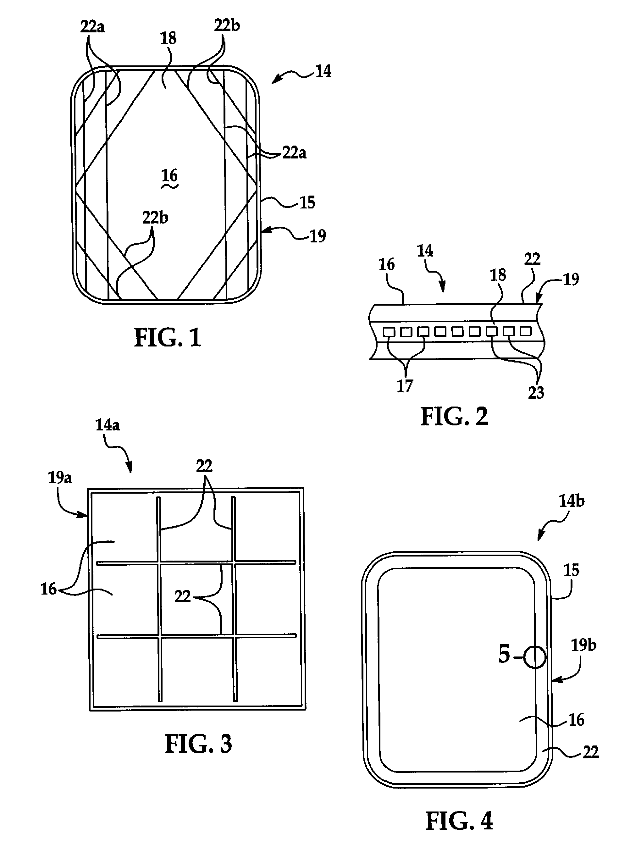
[0006]FIG. 1 is a front view of a composite material in the form of a structural window, illustrating an illustrative reinforcing opaque region pattern in the composite material.

[0007]FIG. 2 is a cross-sectional view of a transparent region and an adjacent opaque region of the structural window.

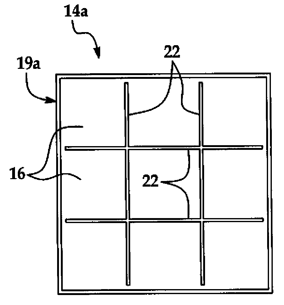
[0008]FIG. 3 is a front view of another illustrative embodiment of the composite material in the form of a structural window, illustrating an alternative, grid-shaped illustrative reinforcing opaque region pattern in the composite material.

[0009]FIG. 4 is a front view of a structural window which includes a composite material having a central transparent region and an outer opaque region.

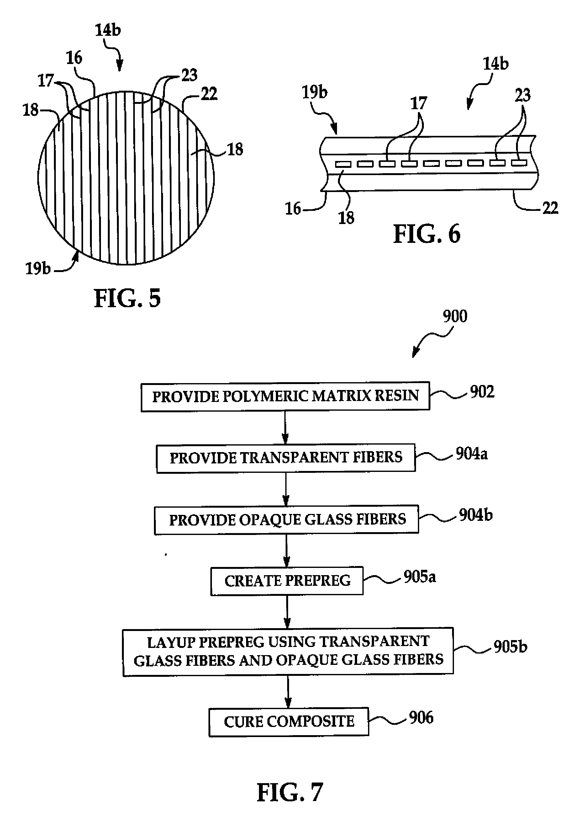
[0010]FIG. 5 is an enlarged sectional view, taken along section line 5 in FIG. 4, with reinforcing opaque elements in the opaque region oriented in generally parallel relationship with respect to optically clear elements in the transparent region of the composite material.

[0011]FIG. 6 is a cross-sectional view o


PUM

PropertyMeasurementUnit
Transparencyaaaaaaaaaa

Abstract

A composite material includes a polymeric matrix, at least one transparent region including a plurality of optically clear elements provided in the polymeric matrix and at least one opaque region including a plurality of opaque reinforcing elements provided in the polymeric matrix generally adjacent to the at least one transparent region. A structural window and a method for reinforcing a composite material are also disclosed.

Description


Claims


Application Information

Patent Timeline
Owner THE BOEING CO
Why Eureka
Try Eureka