Flexible battery restraint for electronic devices

a technology of electronic devices and restraints, applied in the direction of cell components, electrical equipment, cell component details, etc., can solve the problems of battery compartment doors being damaged or lost, battery inside these devices falling out and/or being dislodged, and being fairly common

Inactive Publication Date: 2010-05-27
PROPEL IP
View PDF1 Cites 9 Cited by
  • Summary
  • Abstract
  • Description
  • Claims
  • Application Information

AI Technical Summary

Benefits of technology

This patented technology allows for easy removal of batteries from electronic devices like TVs without damaging them during maintenance work on their housings. It involves attaching a special material called a soft lining onto top of the battery's case inside the casing. These materials have small holes near its ends where they are attached securely by being tightened around it when installed properly.

Problems solved by technology

The technical problem addressed in this patented text relates to damage caused during maintenance procedures on electronic devices due to their usage over time. These issues are particularly challenged with older models where they were replaced after being used once again without replacing them properly. Additionally, there have been attempts at create solutions involving more affordably replaceable spare parts rather than requiring an entire machine altogether.

Method used


Image

  • Flexible battery restraint for electronic devices
  • Flexible battery restraint for electronic devices
  • Flexible battery restraint for electronic devices

Examples


Embodiment Construction

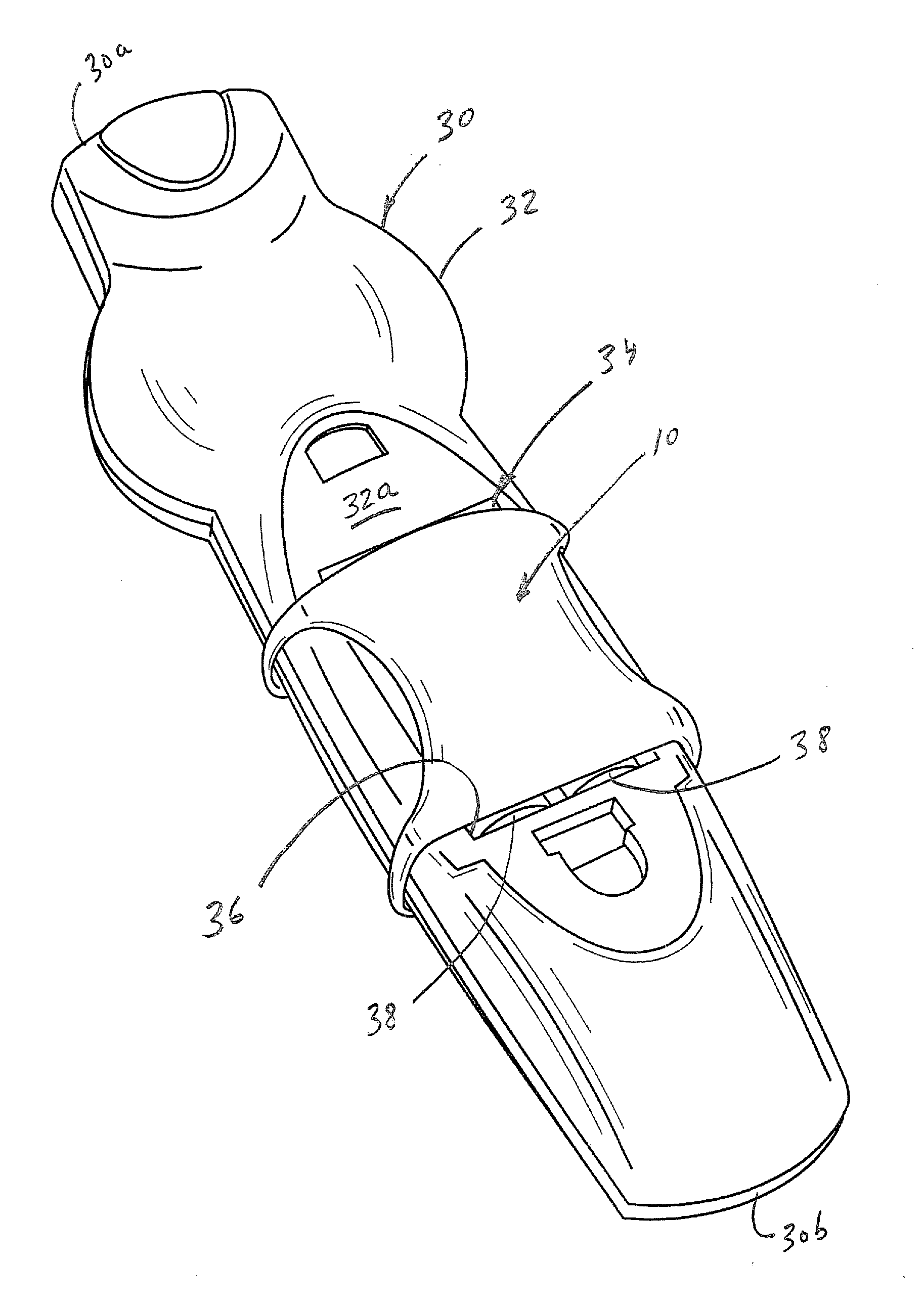
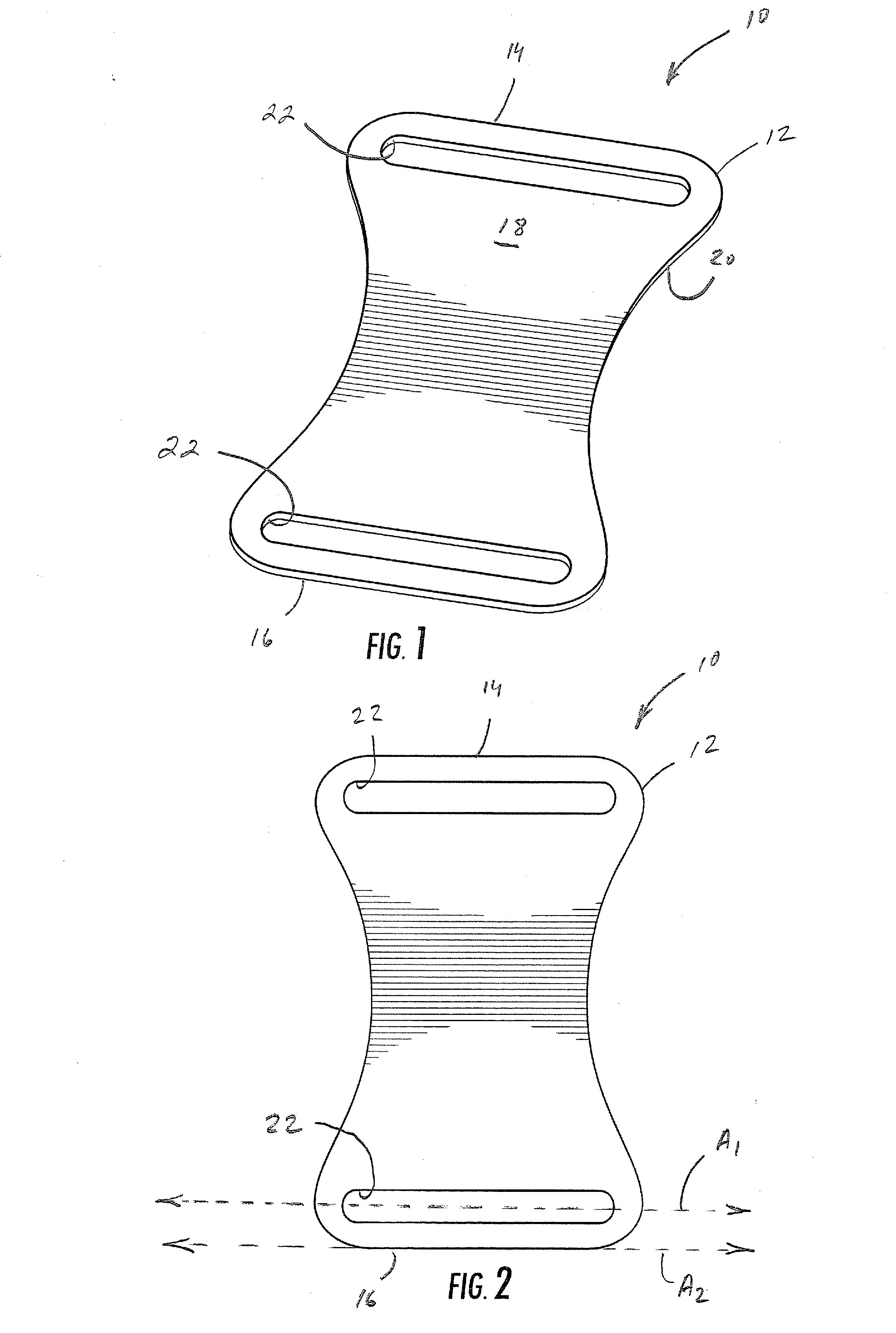
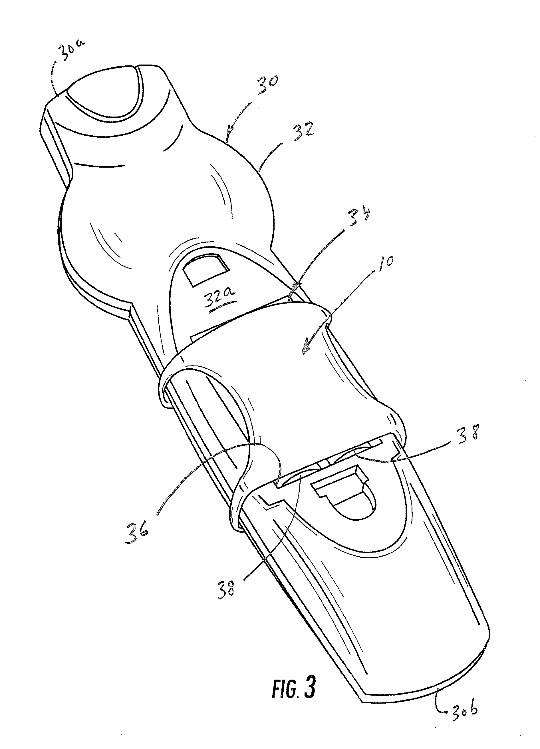
[0015]While the invention is susceptible to various modifications and alternative forms, specific embodiments thereof are shown by way of example in the drawings and will herein be described in detail. It should be understood, however, that there is no intent to limit the invention to the particular forms disclosed, but on the contrary, the invention is to cover all modifications, equivalents, and alternatives falling within the spirit and scope of the invention as defined by the claims. Like reference numbers signify like elements throughout the description of the figures.

[0016]As used herein, the singular forms “a,”“an,” and “the” are intended to include the plural forms as well, unless expressly stated otherwise. It should be further understood that the terms “comprises” and / or “comprising” when used in this specification are taken to specify the presence of stated features, steps, operations, elements, and / or components, but do not preclude the presence or addition of one or mo


PUM


Abstract

A battery restraint apparatus for electronic devices includes a flexible, resilient substrate having opposite, elongated end portions. An elongated aperture is formed in the substrate adjacent each end portion. The substrate has elastic memory that allows it to be flexed and bent and to thereafter resiliently recover to its original shape. The battery restraint apparatus is configured to be removably secured to an electronic device and snugly overlie a battery compartment opening thereof.

Description


Claims


Application Information

Patent Timeline
Owner PROPEL IP
Why Eureka
Try Eureka