Piston apparatus of automatic transmission

a technology of automatic transmission and piston, which is applied in the direction of mechanical actuated clutches, machines/engines, and gearing, etc., can solve the problems of a large number of parts, and achieve the effect of reducing the size of the automatic transmission and reducing the cos

Inactive Publication Date: 2010-06-10
TOYOTA JIDOSHA KK
View PDF6 Cites 8 Cited by
  • Summary
  • Abstract
  • Description
  • Claims
  • Application Information

AI Technical Summary

Benefits of technology

The technical effect of this patented technology is that it allows for better efficiency in automobile design while minimizing costs. By using less expensive materials like metal or plastic instead of more expensive ones, the size of the gearbox may also be reduced without compromising its performance.

Problems solved by technology

The technical problem addressed in this patent is how to improve the durability of the connection between the pressing part of a piston mechanism and the connecting part of the piston body during operation of the automatic transmission without increasing its size.

Method used


Image

  • Piston apparatus of automatic transmission
  • Piston apparatus of automatic transmission
  • Piston apparatus of automatic transmission

Examples


Embodiment Construction

[0026]Below is a description of an embodiment of the present invention with reference to the attached drawings.

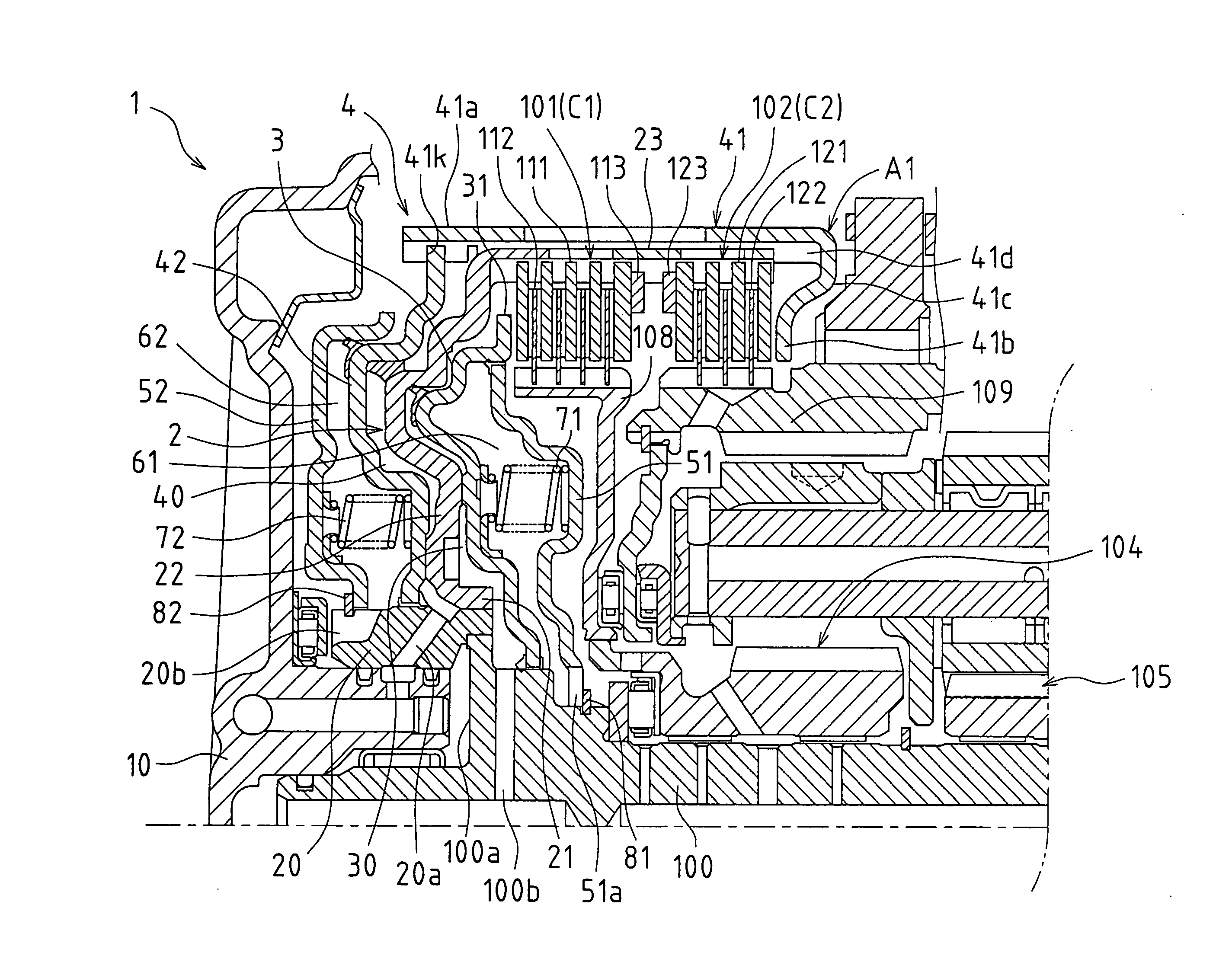
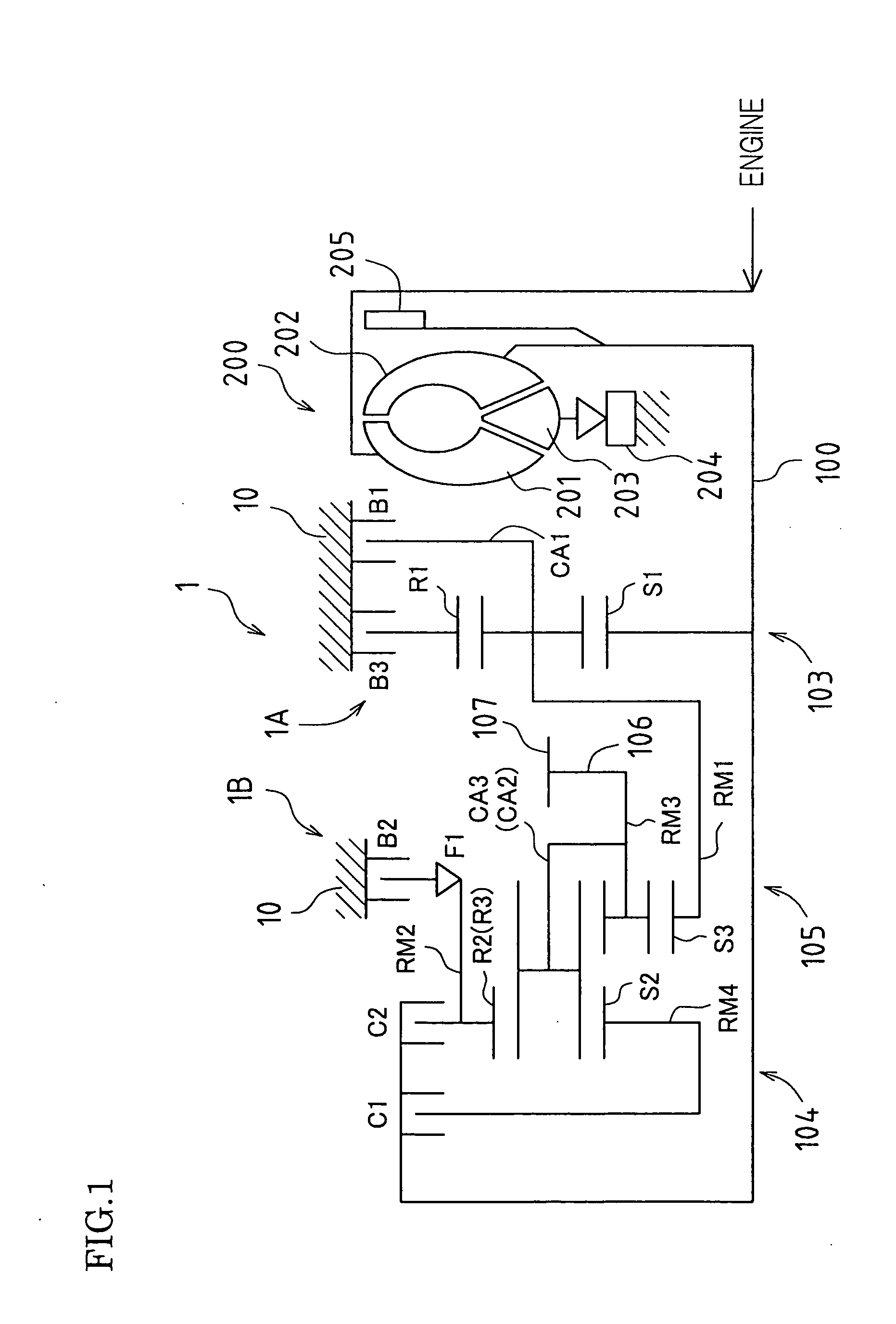
[0027]FIG. 1 is a schematic diagram showing an automatic transmission (including a torque converter) according to an embodiment to which a piston apparatus of the present invention is applied.

[0028]FIG. 1 shows an automatic transmission 1 included in an FF (Front-engine, Front-wheel drive) vehicle. Note that since the automatic transmission 1 is configured substantially symmetrically with respect to a center line, the lower half below the center line has been omitted in FIG. 1.

[0029]Firstly, a torque converter 200 is a fluid transmission apparatus that performs power transmission between an input shaft side and an output shaft side via a fluid. The torque converter 200 includes a pump impeller 201 on the input shaft side, a turbine runner 202 on the output shaft side, a stator 203 that realizes a torque amplification function, and a one-way clutch 204.

[0030]The torque converte


PUM


Abstract

In an embodiment of the present invention, a piston apparatus of an automatic transmission includes a piston member capable of moving in the axial direction of the rotation shaft, and a hydraulic chamber, and has been configured so that the piston member moves in the axial direction due to pressure in the hydraulic chamber. The piston member includes a cylinder part that extends in the axial direction and to which pressure in the hydraulic chamber is transmitted, a pressing part that extends in the radial direction and presses against a friction engaging element of the automatic transmission, and a connecting part that connects the cylinder part and the pressing part and, with respect to the axial direction, is offset from the pressing part in a direction of separation from the friction engaging element. Also, the axial direction offset amount of the connecting part from the pressing part of the piston member has been set larger than the stroke amount of the piston member.

Description


Claims


Application Information

Patent Timeline
Owner TOYOTA JIDOSHA KK
Why Eureka
Try Eureka