Agricultural Vehicle Suspension

Active Publication Date: 2010-09-02
BLUE LEAF I P
View PDF19 Cites 13 Cited by
  • Summary
  • Abstract
  • Description
  • Claims
  • Application Information

AI Technical Summary

Benefits of technology

[0019]According to a further embodiment of the present invention the suspension units are paired in the manner proposed in EP 1 419 956. In this way, the volume of fluid that needs to be displaced by the actuator to change the attitude of the cab is reduced because one of the suspension units will supply at least some of the fluid required by the other.

Problems solved by technology

While such a cab suspension goes some way towards improving the ride quality in the cab, it still suffers from the disadvantage that when the tractor is being driven along an incline, the cab and the driver's seat, though parallel to the ground, are inclined relative to the horizontal and this causes discomfort to the driver, aside from being disconcerting.
Similarly, when the tractor is being driven up or down an incline the cab can assume an extra-pitch angle causing discomfort to the driver.
In this known system, the fact that all four actuators can be independently controlled makes for a complicated control system.
This is because the control algorithm needs to take into account when an actuator is near the bottom or top of its stroke and is therefore unable to bring about the required tilt of the cab.
A disadvantage of U.S. Pat. No. 6,273,203, U.S. Pat. No. 7,198,125 and other prior art cab suspension systems which use hydraulic dampers as actuators to level the cab stems from the fact that they require a dedicated pumping unit.

Method used


Image

  • Agricultural Vehicle Suspension
  • Agricultural Vehicle Suspension
  • Agricultural Vehicle Suspension

Examples


Example

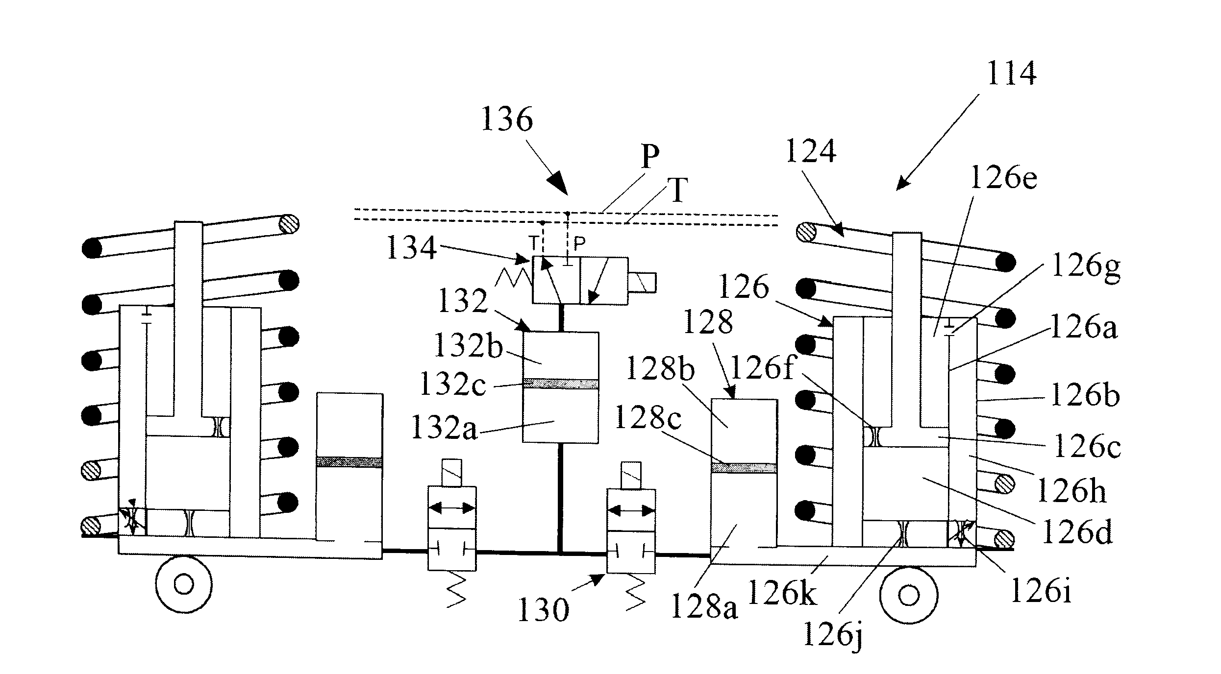
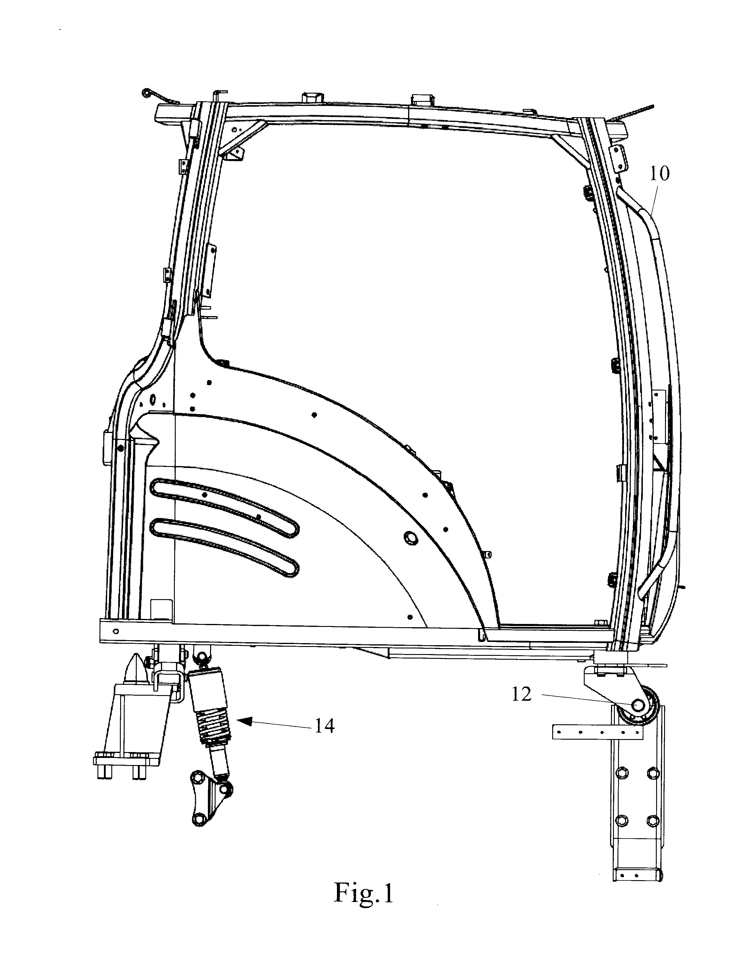
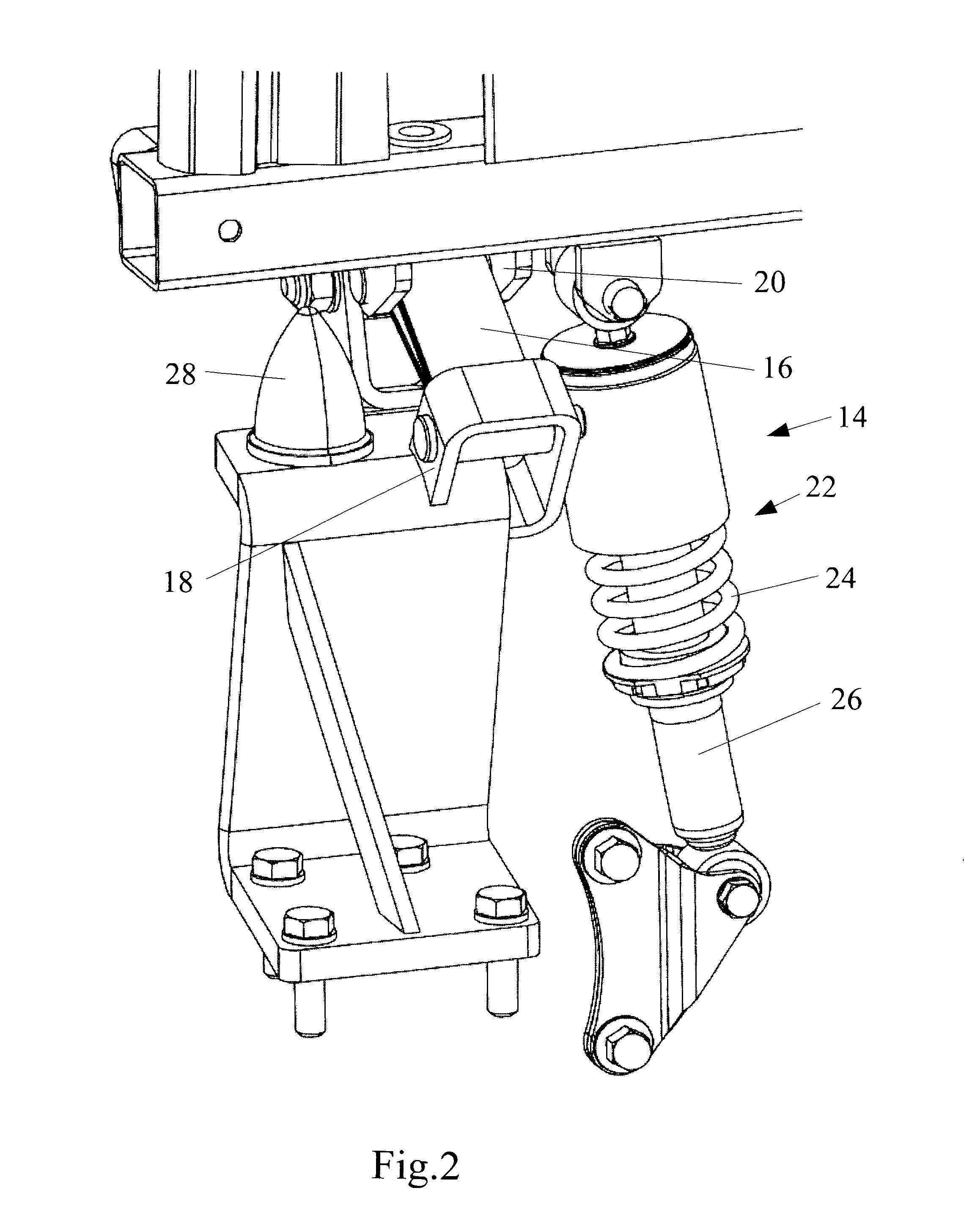
[0024]While the invention can be used in a cab suspension as shown in FIGS. 1 and 2 it is also possible to provide suspension units at the four corners of the cab to control pitch and roll. The hydraulic circuits shown in FIGS. 3 and 4 each show one pair of suspension units. It is also possible to couple the suspension units in pairs in the manner previously proposed in U.S. Pat. No. 7,198,125.

[0025]The two suspension units 114 in FIG. 3 are identical with one another and only one of them will therefore now be described. Each suspension unit comprises an adjustable damper 126, such as for example a variable stiffness damper, a coil spring 124 surrounding the damper 126, a hydro-gas accumulator 128 and an isolation valve 130. The two suspension units 114 are connected to a common actuator 132 which in turn is connected by way of a changeover valve 134 to the supply and return lines P and T of the vehicle hydraulic system 136.

[0026]The damper 126 can be, for example, a twin tube damper h


PUM


Abstract

An agricultural vehicle having a hydraulic system, a cab for the vehicle operator includes a self-levelling cab suspension system having a plurality of suspension units each having a spring, a damper and an accumulator. The accumulator comprises a hydraulic working chamber which is separated by a movable wall from a gas filled chamber serving as a spring. The working chamber is also connected to a working chamber of the damper in a closed hydraulic circuit. In the invention, there is no need for a dedicated oil pump since a hydraulic actuator powered by the vehicle hydraulic system is provided for causing hydraulic fluid to flow in the closed hydraulic circuit between the working chamber of the accumulator and the damper, to vary the height of the cab without fluid from the vehicle hydraulic system entering or leaving the closed hydraulic circuit of the damper and accumulator.

Description


Claims


Application Information

Patent Timeline
Owner BLUE LEAF I P
Why Eureka
Try Eureka