Spiral staircase

a spiral staircase and spiral technology, applied in the direction of stairs, staircases, building constructions, etc., can solve the problems of difficult operation, difficult to reach the end of the steps, and the surface available for supporting the sole of the foot, so as to facilitate the ascending and descending of the spiral staircase. , the effect of increasing the number of steps

Inactive Publication Date: 2011-10-27
ALBINI & FONTANOT
View PDF7 Cites 1 Cited by
  • Summary
  • Abstract
  • Description
  • Claims
  • Application Information

AI Technical Summary

Benefits of technology

The present invention improves the stability and balance of walking up and down a spiral staircase by increasing the surface area on both feet while also allowing for equal support for each foot's legs. This makes it easier for people who are more stable at different levels of their body than they could otherwise have had difficulty navigating through them. Additionally, the design ensures there is enough space between the two feet without making them too bulky. Overall, these technical improvements improve the functionality and usability of the walker.

Problems solved by technology

The technical problem addressed in this patent text relates to improving the design of spiral stairs, particularly in smaller spaces where they may have difficulty reaching up or down the staircase due to limitations such as lack of space or instability caused by the small size of the steps.

Method used


Image

  • Spiral staircase
  • Spiral staircase
  • Spiral staircase

Examples


Embodiment Construction

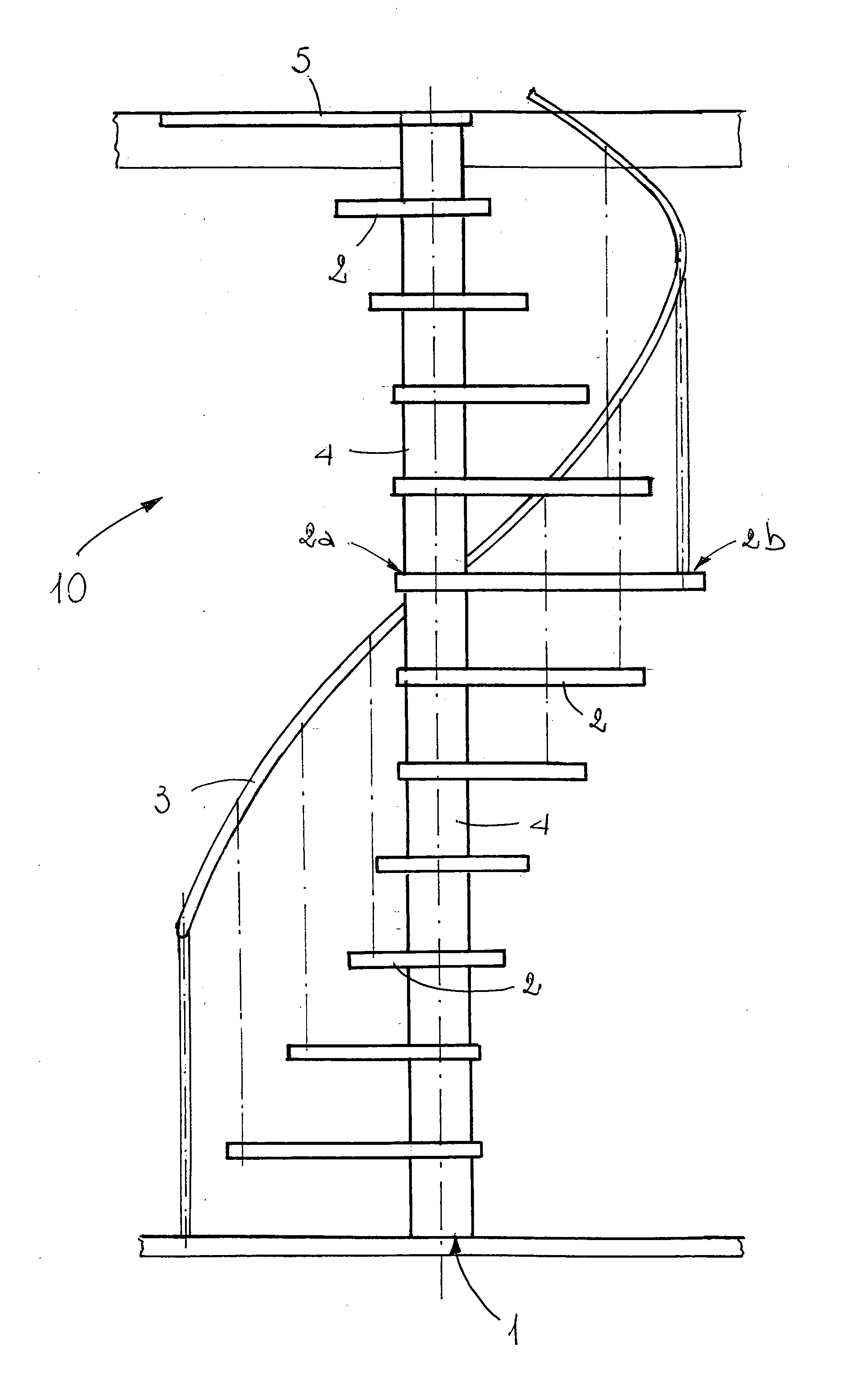
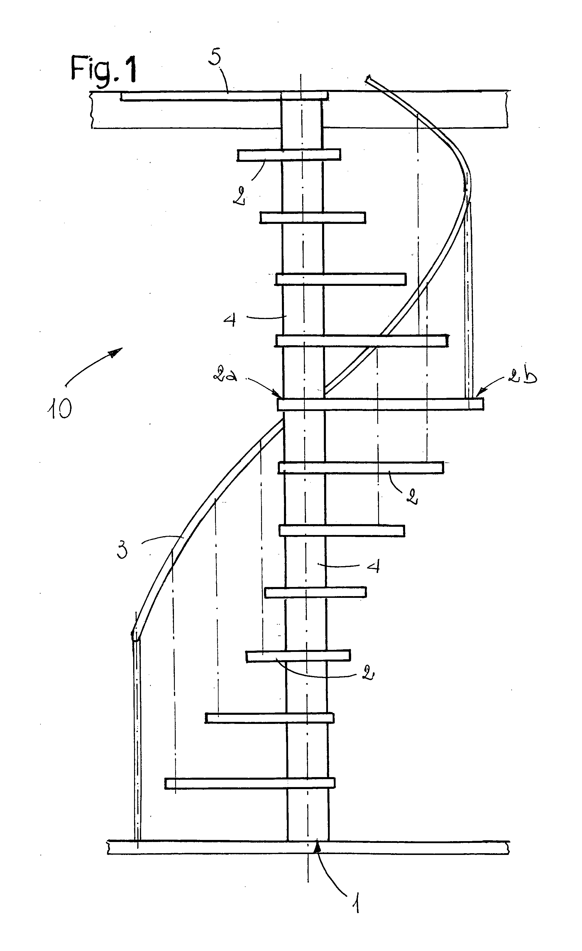
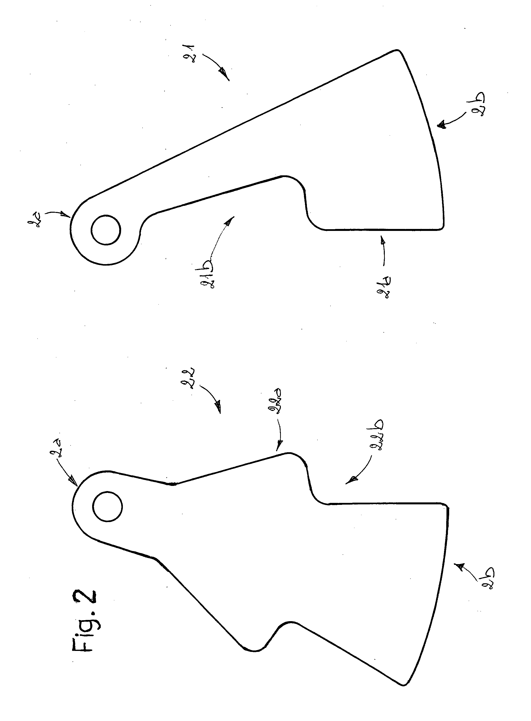
[0018]In accordance with the accompanying drawings, the invention relates to a spiral staircase. It comprises a central supporting element (1) and a plurality of steps (2), which are connected to the supporting element (1) at a first end (2a). In particular, as shown in FIGS. 2 and 4, it comprises two types of steps (21, 22), where a first type of step (21) is substantially “L”-shaped and a second type of step (22) is substantially arrow-shaped. They are positioned along the staircase (10) in an alternating fashion, as shown in the detail in FIG. 3.

[0019]The first type of step (21) comprises at least one projection (21a) and one recess (21b) which complement at least one projection (22a) and one recess (22b) of the second type of step (22). The projections (21a, 22a) and recesses (21b, 22b) contribute to forming on the steps (21, 22) treadable portions (21c, 22c) which are separate from portions (21d, 22d) that are not strictly necessary for achieving the advantages which the invention


PUM


Abstract

A spiral staircase comprises a central supporting element and a plurality of steps which are connected to the supporting element at a first end, there being two types of steps positioned in an alternating fashion, of which a first type of step is substantially “L”-shaped and a second type of step is substantially arrow-shaped.

Description


Claims


Application Information

Patent Timeline
Owner ALBINI & FONTANOT
Why Eureka
Try Eureka